Method and arrangement for forming a dental bridge

a technology of dental bridges and dental implants, applied in the field of dental bridge manufacturing methods and arrangements, can solve the problem that the pre-sintered object has not yet reached the final density

Active Publication Date: 2010-11-18
NOBEL BIOCARE SERVICES AG
View PDF38 Cites 36 Cited by
  • Summary
  • Abstract
  • Description
  • Claims
  • Application Information

AI Technical Summary

Benefits of technology

[0006]The present application relates to a method of manufacturing a dental bridge. In certain embodiments described herein, the method comprises the step of providing a blank in the form of a pre-sintered product that has been formed in an initial first sintering operation. The pre-sintered product may have been formed in a process where a green body is subjected to an elevated temperature. In the context of this application, a green body in certain embodiments should be understood as a ceramic body that has been formed by pressing ceramic powder to a solid body. Due to the first sintering operation, the pressed green body becomes more solid. After the first sintering operation, the green body has been transformed into a pre-sintered object. However, the pre-sintered object has not yet reached its final density. A machining operation is performed on the blank, normally the pre-sintered object, that transforms it to an intermediate product comprising in certain embodiments, a bridge structure and a support body linked to the bridge structure by one or several retaining sections that extend from the support body to the bridge structure. Such retaining sections may be shaped as spokes. A sintering operation is then performed on the intermediate product. In some embodiments, the retaining section or retaining sections still link(s) the bridge structure to the support body during the second sintering operation, thereby supporting the bridge structure during the second sintering operation. The retaining sections may be removed from the bridge structure after the second sintering operation. Optionally, the method may be performed in such a way that, during the second sintering operation, the intermediate product has been placed such that the retaining sections(s) extend(s) at least partially in a vertical direction.

Problems solved by technology

However, the pre-sintered object has not yet reached its final density.

Method used


Image

  • Method and arrangement for forming a dental bridge
  • Method and arrangement for forming a dental bridge
  • Method and arrangement for forming a dental bridge

Examples


Embodiment Construction

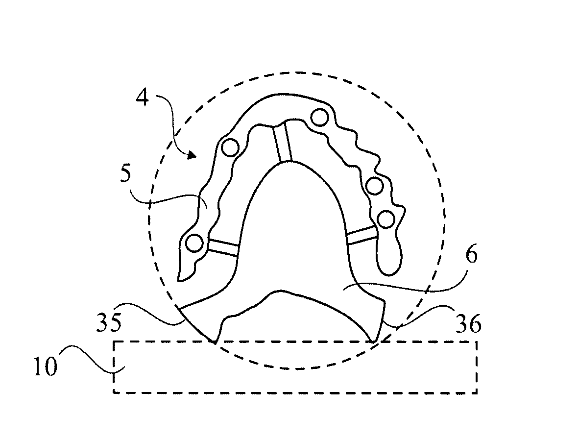
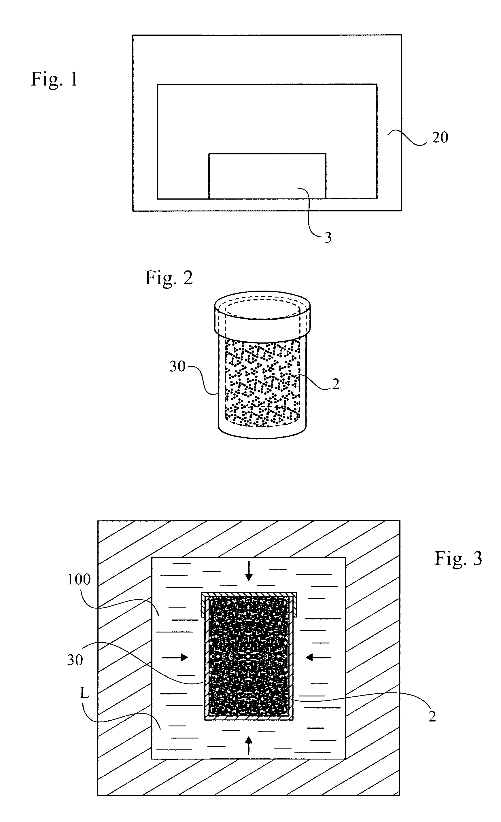
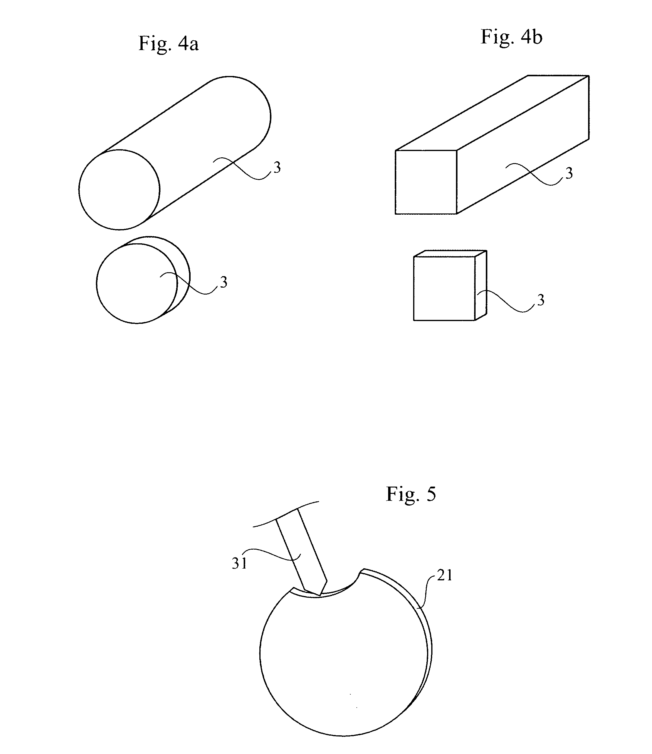
[0029]With reference to FIG. 1 , a method for manufacturing a dental bridge may comprise subjecting an object 3 to a first sintering operation where sintering can be performed in a sintering furnace 20. The first sintering operation can be understood as pre-sintering where the object 3 does not reach its final density. Typically, the density of the object 3 increases only slightly during the first sintering operation and in some cases it may actually be so that density does not at all increase during the first sintering operation. During the first sintering operation, the object that is sintered may be subjected to a temperature of, for example, about 800° C.-1200° C. for a period of 1-2 hours. The object 3 that is sintered is made of a ceramic powder material 2, for example zirconium oxide or aluminum oxide. Before the sintering operation, the powder material 2 may have been compressed in a mold 30 into a solid green body as indicated in FIG. 2. The mold 30 may be, for example, a m...


PUM

PropertyMeasurementUnit
temperatureaaaaaaaaaa

Abstract

Certain embodiments of the invention relate to a method of manufacturing a dental bridge. In certain embodiments of the method, a pre-sintered blank made from a green body of ceramic material is subjected to a machining operation that transforms the blank into an intermediate product with a bridge structure and a support body linked to the bridge structure by one or several retaining sections that extend from the support body to the bridge structure. In certain embodiments, a sintering operation is then performed on the intermediate product while the retaining section(s) still link(s) the support body to the bridge structure.

Description

CROSS-REFERENCE TO RELATED APPLICATIONS[0001]This application is a national stage application under 35 U.S.C. §371 of PCT Application No. PCT / EP2008 / 004245, filed on May 29, 2008, which published in English as WO 2008 / 148495 A1 on Dec. 11, 2008 and which claims priority benefit of European Patent Application No. 7011196-8, filed on Jun. 7, 2007, the entire contents of which applications and publication are herein incorporated by reference in their entirety.BACKGROUND[0002]1. Field of the Invention[0003]The present application relates to a method and an arrangement for manufacturing a dental bridge of the kind used to replace missing teeth in the mouth of a patient. The application also relates to an intermediate product used in the process of manufacturing such a dental bridge.[0004]2. Description of the Related Art[0005]Dental bridges are used to replace missing teeth on a patient's jaw. Such a bridge may be manufactured in a process that includes sintering of powder into a body th...

Claims


Application Information

Patent Timeline
Patent Type & Authority Applications(United States)
IPC IPC(8): A61C13/003A61C5/77
CPCA61C13/0003Y10T29/49567A61C13/12A61C13/0022
Inventor BERGGREN, CARINAJORNEUS, LARSJOHANSSON, ULFBRANNVALL, PETRUSVOGEL, OLOF
Owner NOBEL BIOCARE SERVICES AG
Why Eureka
Try Eureka