
Method and Apparatus for Physical Confinement of a Liquid Meniscus over a Semiconductor Wafer

a liquid meniscus and semiconductor wafer technology, applied in the field of physical confinement of liquid meniscus on the surface of the semiconductor wafer, can solve the problems of substantial loss of liquid chemistry due to evaporation, high cost of liquid chemistry used in the cleaning process, and loss of liquid chemistry adding to the cost of cleaning, so as to preserve the confinement characteristics of liquid chemistry

Inactive Publication Date: 2010-12-02
LAM RES CORP
View PDF9 Cites 8 Cited by
  • Summary
  • Abstract
  • Description
  • Claims
  • Application Information

AI Technical Summary

Benefits of technology

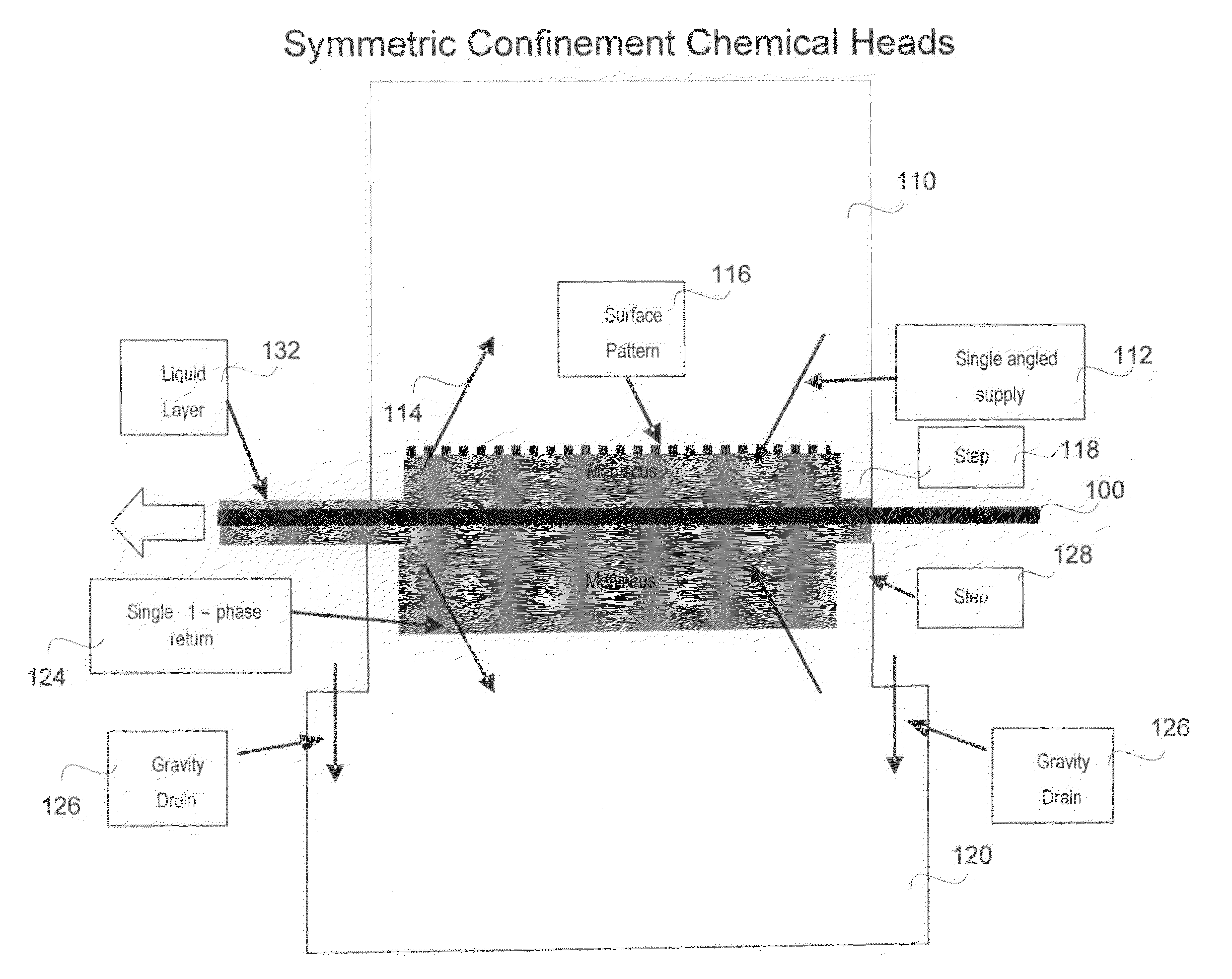
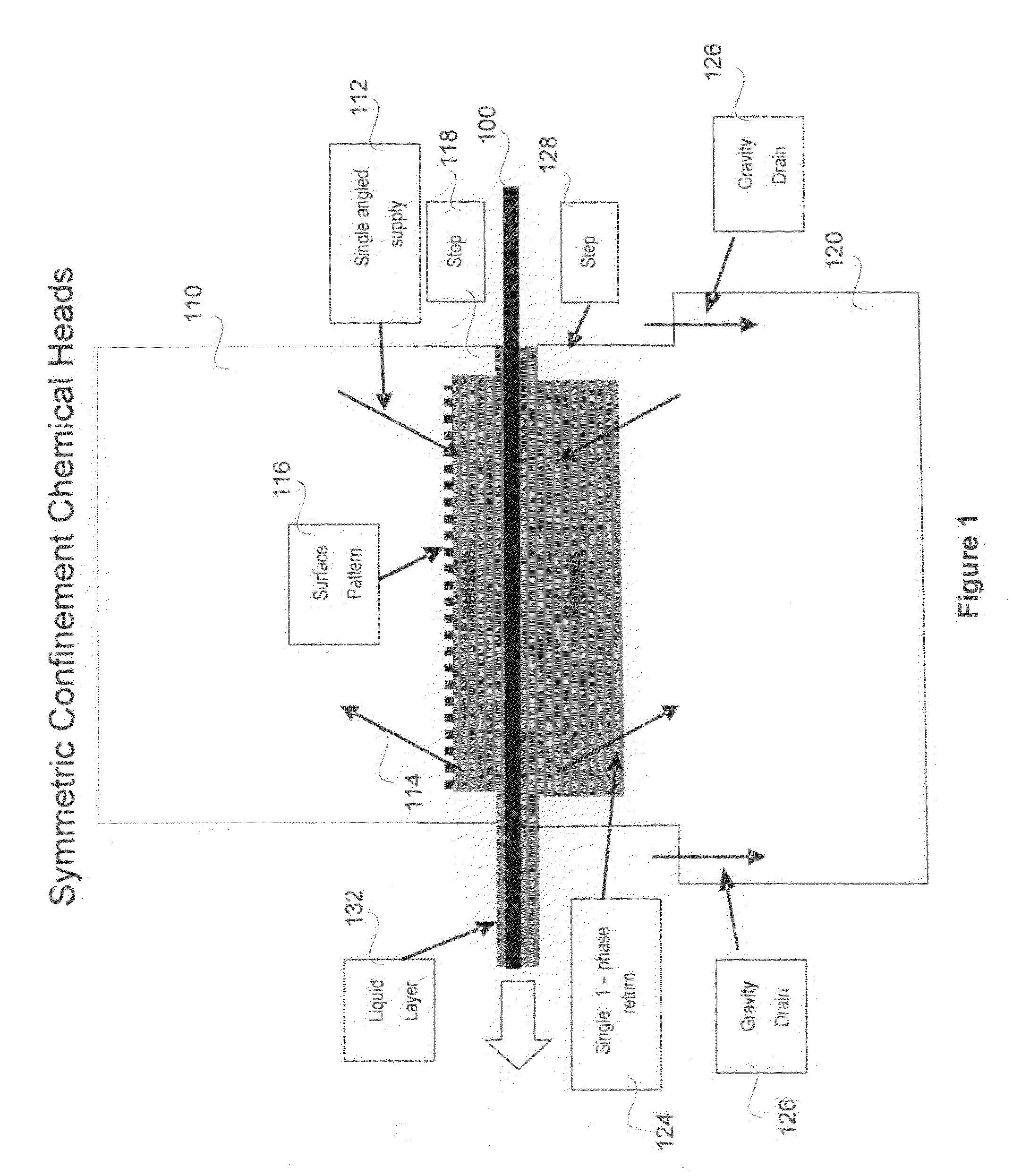
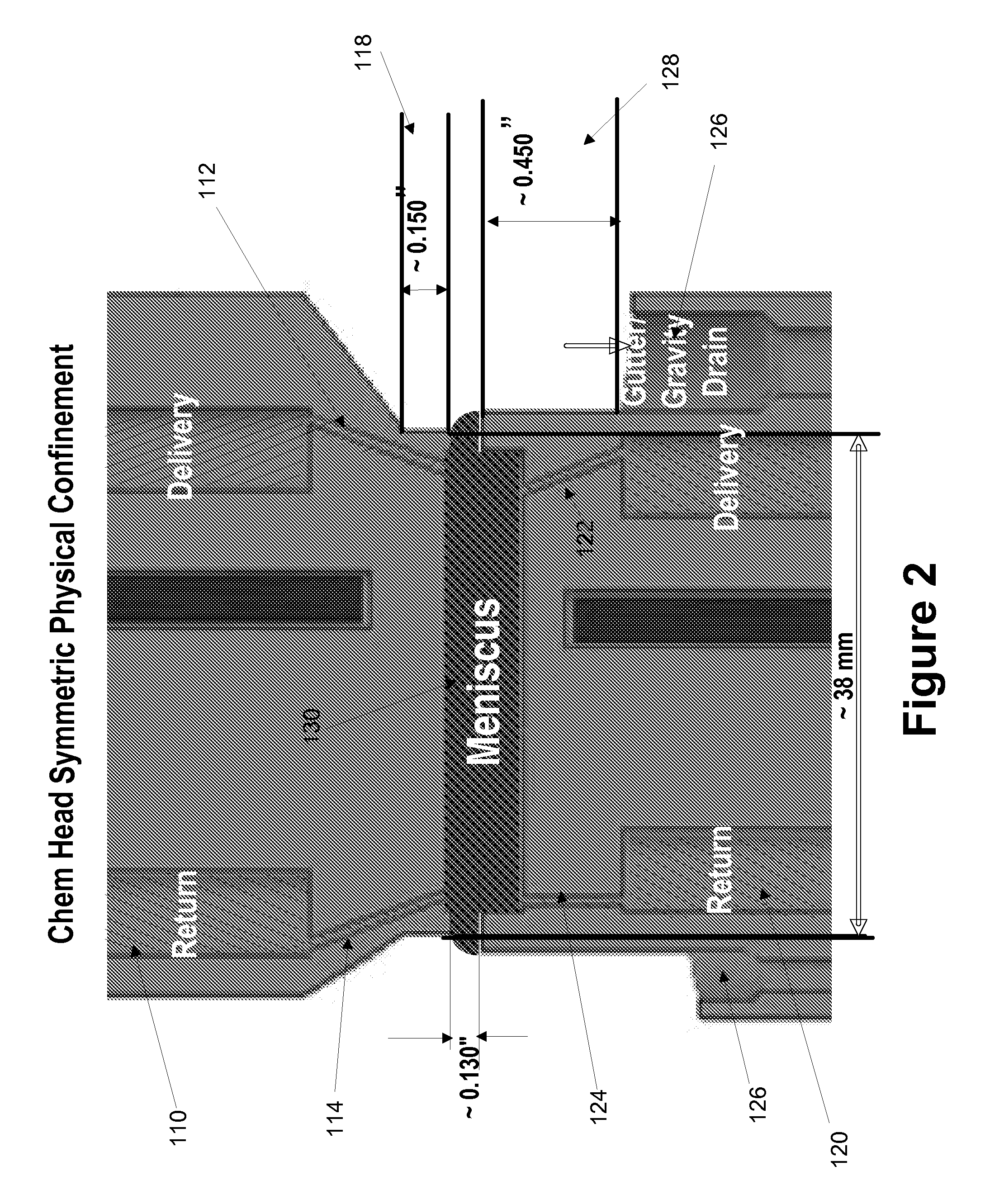
[0012]In one embodiment, a method for physically confining a liquid medium meniscus over a semiconductor wafer, is provided. The method includes delivering a liquid chemistry into a pocket of meniscus defined on a surface of the semiconductor wafer. The pocket of meniscus is defined between a first and a second chemical head. The liquid chemistry is delivered into the pocket of meniscus in a single phase through angled inlet conduits defined at the first and second chemical heads, respectively. A step is defined along at least a portion of an outer periphery of the pocket of meniscus such that the height of the step is sufficient to preserve the confinement characteristics of the liquid chemistry. The liquid chemistry is removed through inner return conduits. The inner return conduits are defined at a trailing edge of the first and second chemical heads within the pocket of meniscus such that the liquid chemistry may be removed from the semiconductor wafer surface in a single phase.
[0013]In another embodiment, an apparatus for physically confining a liquid medium applied over a semiconductor wafer, is provided. The apparatus includes a first and a second chemical head that are disposed to cover at least a portion of a top and an underside surface of the semiconductor wafer. Each of the first and the second chemical heads includes an angled inlet conduit at a leading edge of the respective chemical heads so as to deliver liquid chemistry into a pocket of meniscus in a single phase. The pocket of meniscus is defined over the portion of the top and underside surface of the semiconductor wafer covered by the chemical heads. The pocket of meniscus is configured to receive and contain the liquid chemistry applied to the surface of the semiconductor wafer as a meniscus. A step is formed along an outer periphery of the pocket of meniscus at a leading edge of the first and second chemical heads so as to substantially confine the meniscus of the liquid chemistry within the pocket of meniscus. The step is defined such that at least a portion of the pocket of meniscus is covered by the step and step's height is sufficient to preserve confinement characteristic of the meniscus. An inner return conduit is located within the pocket of meniscus at a trailing edge of the respective chemical heads. The inner return conduit is used to remove the liquid chemistry from the surface of the semiconductor wafer in a single phase after the cleaning process.
[0015]The advantages of using the mechanism include substantial reduction or elimination of air flow to contain the meniscus. Eliminating air flow during containment results in preserving liquid chemistry which would have been otherwise lost due to evaporation. The process allows for simpler tuning to preserve the confinement and other characteristics of the liquid meniscus. By preserving the characteristics of the liquid chemistry, optimal chemical clean can be achieved without considerable damage to the wafer. Further, the mechanism allows for reclaiming and reusing the costly liquid chemistry, thereby making this a more cost-effective and efficient cleaning solution.

Problems solved by technology

For instance, the liquid chemistry is exposed to the large air flow resulting in substantial loss of the liquid chemistry due to evaporation.
Some of the liquid chemistry used in the cleaning process is very expensive and any loss of liquid chemistry adds to the cost of cleaning.
Evaporation of the liquid chemistry in conventional cleaning processes is a serious issue, especially when using proximity heads.
Specifically, due to high ambient air flow through the proximity heads, it is difficult to control evaporation loss of the liquid chemistry.
Liquid chemistry loss can dramatically increase when liquid chemistry is applied at a higher temperature.
As a result, the amount of liquid chemistry that can be reclaimed for reuse dramatically decreases.
However, static temperature gradient that naturally develops because of higher temperature of the liquid chemistries cause these cleaning apparatus to deform resulting in mediocre operation of the apparatus during cleaning.
Another disadvantage of the use of air for confining the meniscus is the cost of generating vacuum in the presence of this large flow of air.
Moreover, evaporation can result in significant changes in the cleaning process by liquid chemistry due to the chemical depletion or change in concentration of the liquid chemistry.
Chemical depletion occurs when the ambient air flow mixes with the hot liquid chemistry resulting in vapor that is saturated with air and components of the liquid chemistry making it hard to isolate and reclaim the liquid chemistry.
This increase in the concentration of non-volatile components can adversely affect the cleaning performance of the liquid chemistry.
Moreover, if the concentration of the liquid chemistry increases too much, there might be significant damage to the semiconductor wafer.

Method used


Image

  • Method and Apparatus for Physical Confinement of a Liquid Meniscus over a Semiconductor Wafer
  • Method and Apparatus for Physical Confinement of a Liquid Meniscus over a Semiconductor Wafer
  • Method and Apparatus for Physical Confinement of a Liquid Meniscus over a Semiconductor Wafer

Examples


Embodiment Construction

[0027]Several embodiments for effectively confining a liquid meniscus over a semiconductor wafer are now described. It will be obvious, however, to one skilled in the art, that the present invention may be practiced without some or all of these specific details. In other instances, well known process operations have not been described in detail in order not to unnecessarily obscure the present invention.

[0028]Embodiments of the invention provide a mechanism for physically confining a liquid meniscus applied to a semiconductor wafer without the use of air flow. The mechanism uses proximity dispense heads with angled inlet conduits to deliver liquid chemical to the surface of the wafer. A pocket of meniscus is defined by a first and a second dispense head on at least a portion of the wafer exposed to the first and second dispense heads. An angled inlet conduit to deliver liquid chemical is defined in the first and second dispense heads such that the liquid chemical can be received wit...


PUM

PropertyMeasurementUnit
temperatureaaaaaaaaaa
step heightaaaaaaaaaa
depthaaaaaaaaaa

Abstract

Apparatus, methods and systems for physically confining a liquid medium applied over a semiconductor wafer include a first and a second chemical head that are disposed to cover at least a portion of a top and an underside surface of the semiconductor wafer. Each of the first and the second chemical heads include an angled inlet conduit at a leading edge of the respective chemical heads to deliver liquid chemistry into a pocket of meniscus in a single phase. The pocket of meniscus is defined over the portion of the top and underside surface of the semiconductor wafer covered by the chemical heads and is configured to receive and contain the liquid chemistry applied to the surface of the semiconductor wafer as a meniscus. A step is formed at a leading edge of the first and second chemical heads along an outer periphery of the pocket of meniscus to substantially confine the meniscus of the liquid chemistry within the pocket of meniscus. The step covers at least a portion of the pocket of meniscus and the step's height is sufficient to preserve confinement characteristic of the meniscus. An inner return conduit is defined within the pocket of meniscus at a trailing edge of the respective chemical heads and is used to remove the liquid chemistry from the surface of the semiconductor wafer in a single phase after the cleaning process.

Description

CROSS REFERENCE TO RELATED APPLICATION[0001]This application is related to U.S. patent application Ser. No. 12 / 194,308 filed on Aug. 19, 2008, and entitled “REMOVING BUBBLES FROM A FLUID FLOWING DOWN THROUGH A PLENUM,” and to U.S. patent application Ser. No. 11 / 532,491, (Attorney Docket No. LAM2P548B) filed on Sep. 15, 2006, entitled “Method and Material for Cleaning a Substrate.” This application is also related to U.S. Patent Application No. 61 / 013950 filed on Dec. 14, 2007, and entitled “MATERIALS AND METHODS FOR PARTICLE REMOVAL BY SINGLE-PHASE AND TWO-PHASE MEDIA.” The aforementioned patent applications are incorporated herein by reference.BACKGROUND OF THE INVENTION[0002]1. Field of the Invention[0003]The present invention relates generally to cleaning of a semiconductor wafer and, more particularly, to physical confinement of a liquid meniscus applied on the surface of the semiconductor wafer during a cleaning process.[0004]2. Description of the Related Art[0005]It is well-kn...

Claims


Application Information

Patent Timeline
Patent Type & Authority Applications(United States)
IPC IPC(8): B08B3/00
CPCB08B3/08Y10T29/494B23P17/04H01L21/67051H01L21/302H01L21/67017
Inventor MAGNI, ENRICOLENZ, ERIC
Owner LAM RES CORP
Learn More