Linear machine

a line-shaped machine and line-shaped technology, applied in the field of line-shaped machines, can solve the problems of not being able to use multi-layer windings, not meeting the requirements of power density and reliability, and not being able to assemble the end connectors with the conductor bars to form the coils

Inactive Publication Date: 2010-12-02
COMPACT DYNAMICS
View PDF8 Cites 9 Cited by
  • Summary
  • Abstract
  • Description
  • Claims
  • Application Information

AI Technical Summary

Problems solved by technology

The known arrangements explained above have the disadvantage that they only partly fulfil the requirements for power density and reliability as set in some application fields.
Also, assembling the end connectors with the conductor bars to form the coils is expensive.
Also, for instance, the design described in EP 1 039 616 A2 does not allow the use of multi-layer windings, since in this case the end connectors would collide with each other.

Method used


Image

  • Linear machine
  • Linear machine

Examples


Embodiment Construction

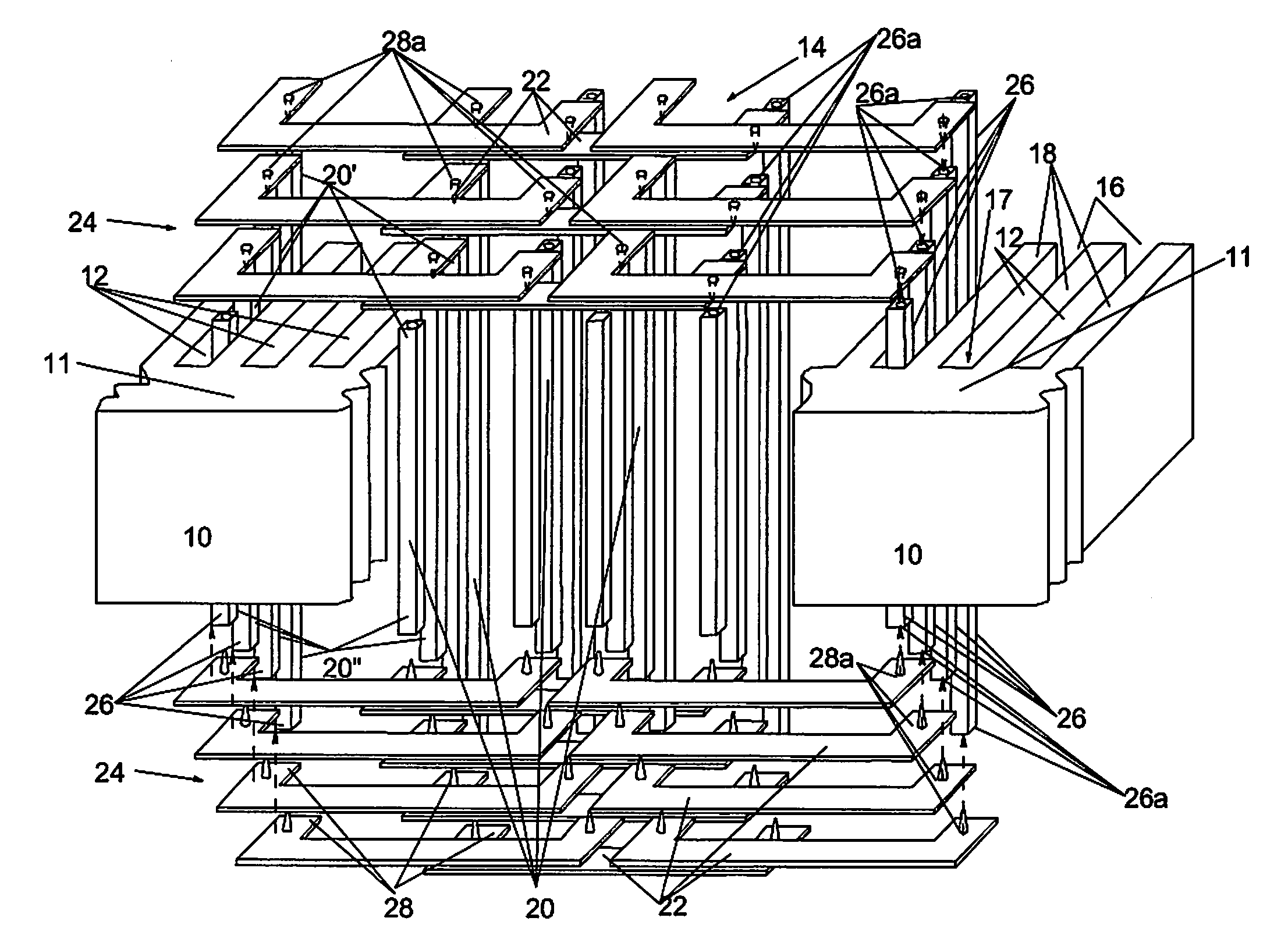
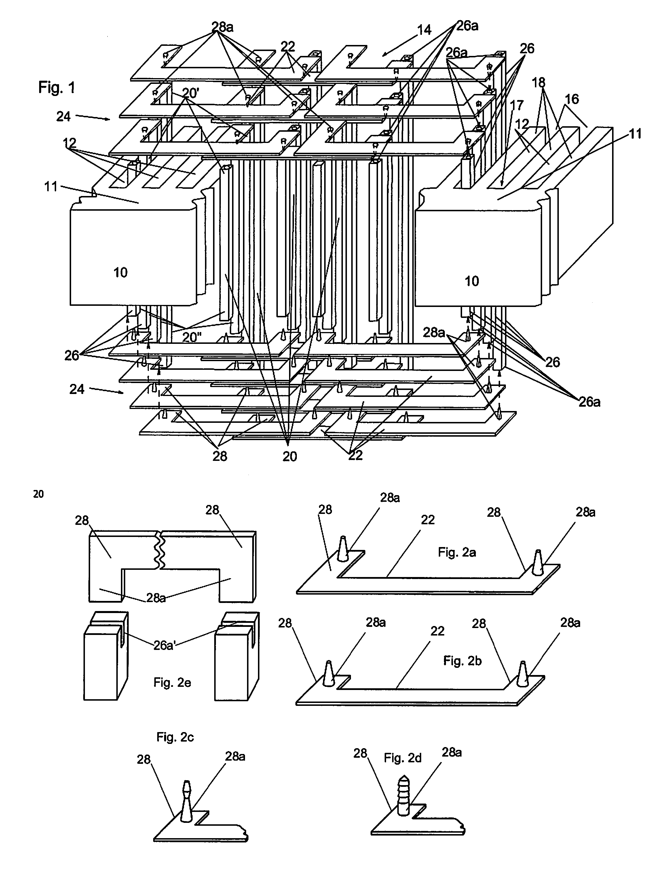
[0024]In FIG. 1, two interrupted sections of a development of a stator 10 of a (not otherwise illustrated) internal rotor machine is shown in a plan view, the invention also being usable for an external rotor machine. In this embodiment, the stator 10 is built up of metal sheets (not otherwise illustrated) stacked one above the other, but it could also consist of iron particles which are pressed and sintered to the corresponding shape.

[0025]The stator 10, with a stator back 11, has grooves 12 which are arranged next to each other, and through which winding chambers for the corresponding stator coil windings 14 are formed. In the shown embodiment, the winding chambers 12 have an essentially rectangular cross-section, and they have slots 16 on their side facing the rotor (not shown). Between each two slots 16, a tooth 18 is formed.

[0026]Each stator coil 14 is formed of conductor bars 20 which are essentially rectangular in cross-section, and which are inserted into the winding chamber...


PUM


Abstract

Linear machine with a stator and a rotor, which are separated by an air gap and have at least one stator coil and/or one rotor coil respectively. The stator or rotor has a soft magnetic iron body with a stator back or rotor back, on which grooves are formed at a distance from each other, forming teeth. In the grooves, multiple conductor bars of the stator coil or rotor coil are arranged in rows. On the faces of the stator or rotor, end connectors which connect the conductor bars and extend over multiple grooves are present. Each conductor bar has a cavity on the face of at least one of its ends. Each end connector has an extension, which is arranged and dimensioned in such a way as to engage in an electrically conducting manner into the respective cavity of the conductor bar, on its section facing the respective front end of the conductor bars.

Description

SCOPE[0001]A linear machine is described below. This is, for instance, a linear machine with a stator and a rotor, which have at least one stator coil and / or one rotor coil respectively, the stator or rotor having a soft magnetic iron body with a stator back or rotor back, on which grooves are formed at a distance from each other, forming teeth.DEFINITION OF TERMS[0002]The term “linear machines”, i.e. asynchronous, synchronous, reluctance machines, permanently excited electrical machines, etc., is understood to mean both motors and generators, whether such a machine is in the form of a rotating machine or, for instance, a linear motor being insignificant. These linear machines can also be used in the case of both internal rotor machines and external rotor machines.BACKGROUND[0003]In reducing the construction space of highly efficient electrical machines, the type and arrangement of the conductors of the field windings have an decisive role. The shortest possible conductor lengths in...

Claims


Application Information

Patent Timeline
Patent Type & Authority Applications(United States)
IPC IPC(8): H02K41/02
CPCH02K3/12
Inventor GRUNDL, ANDREASHOFFMANN, BERNHARD
Owner COMPACT DYNAMICS
Why Eureka
Try Eureka