
Separation of a Fluid Mixture Using Self-Cooling of the Mixture

Inactive Publication Date: 2010-12-16
UOP LLC
View PDF19 Cites 7 Cited by
  • Summary
  • Abstract
  • Description
  • Claims
  • Application Information

AI Technical Summary

Benefits of technology

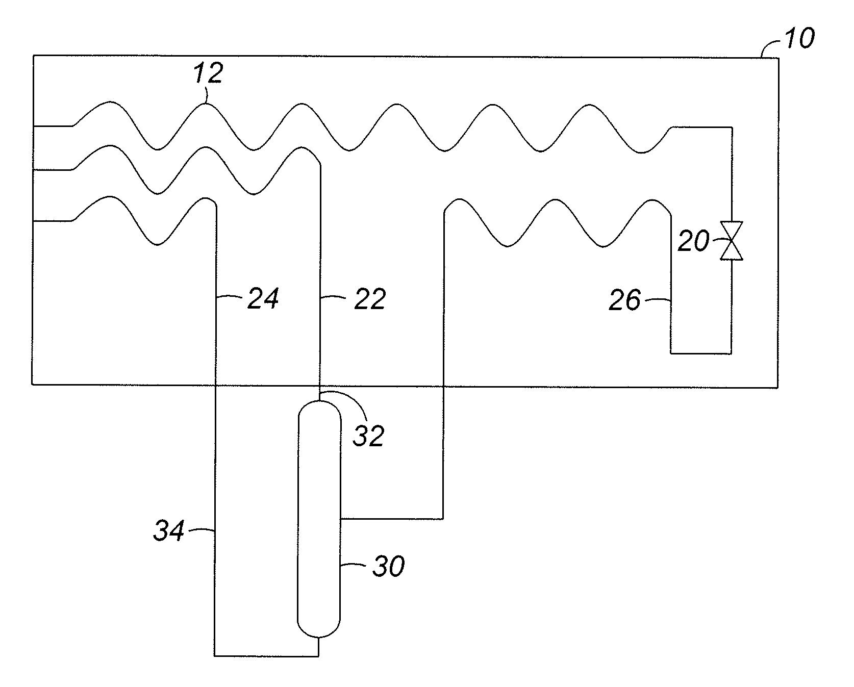
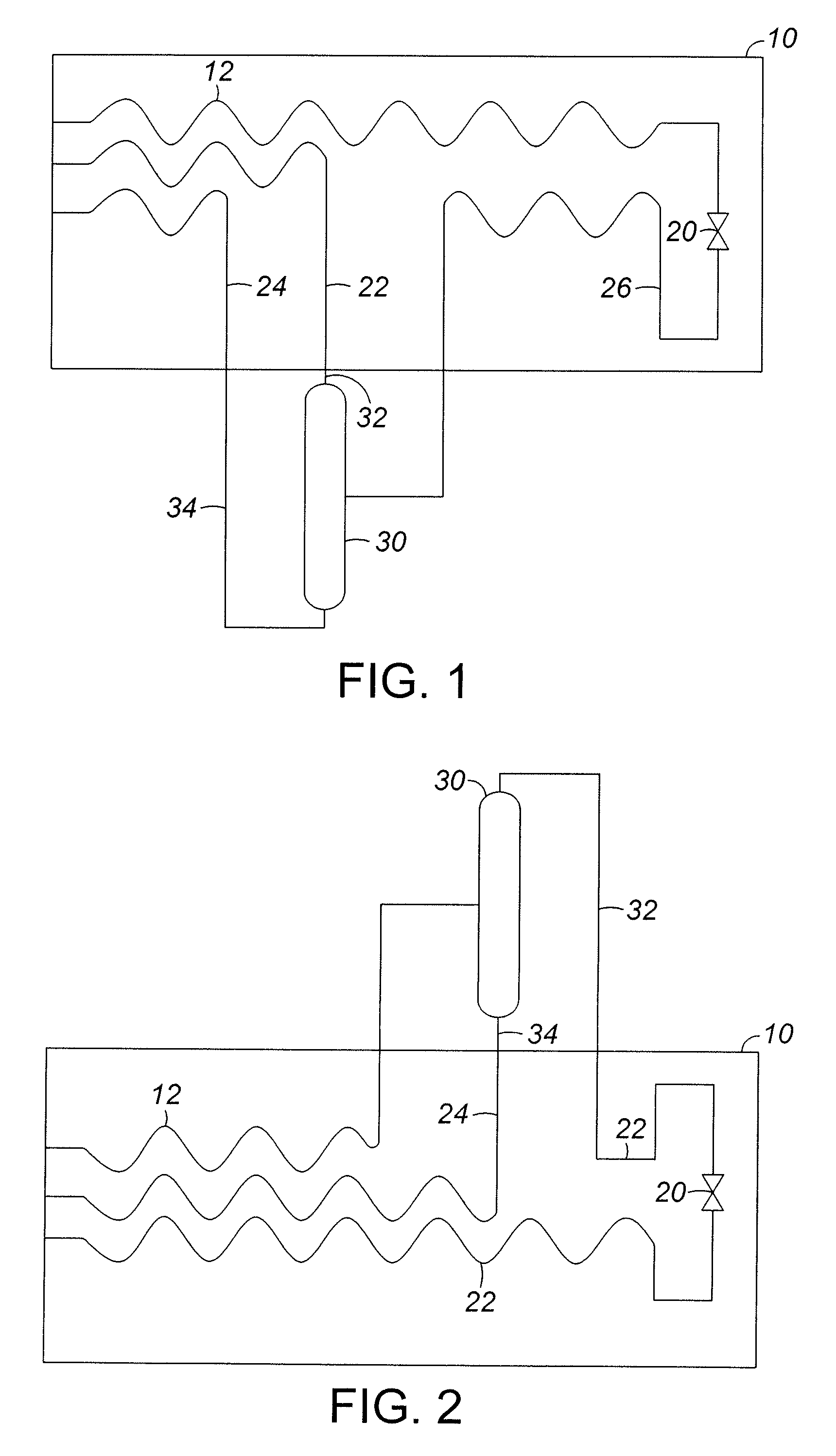
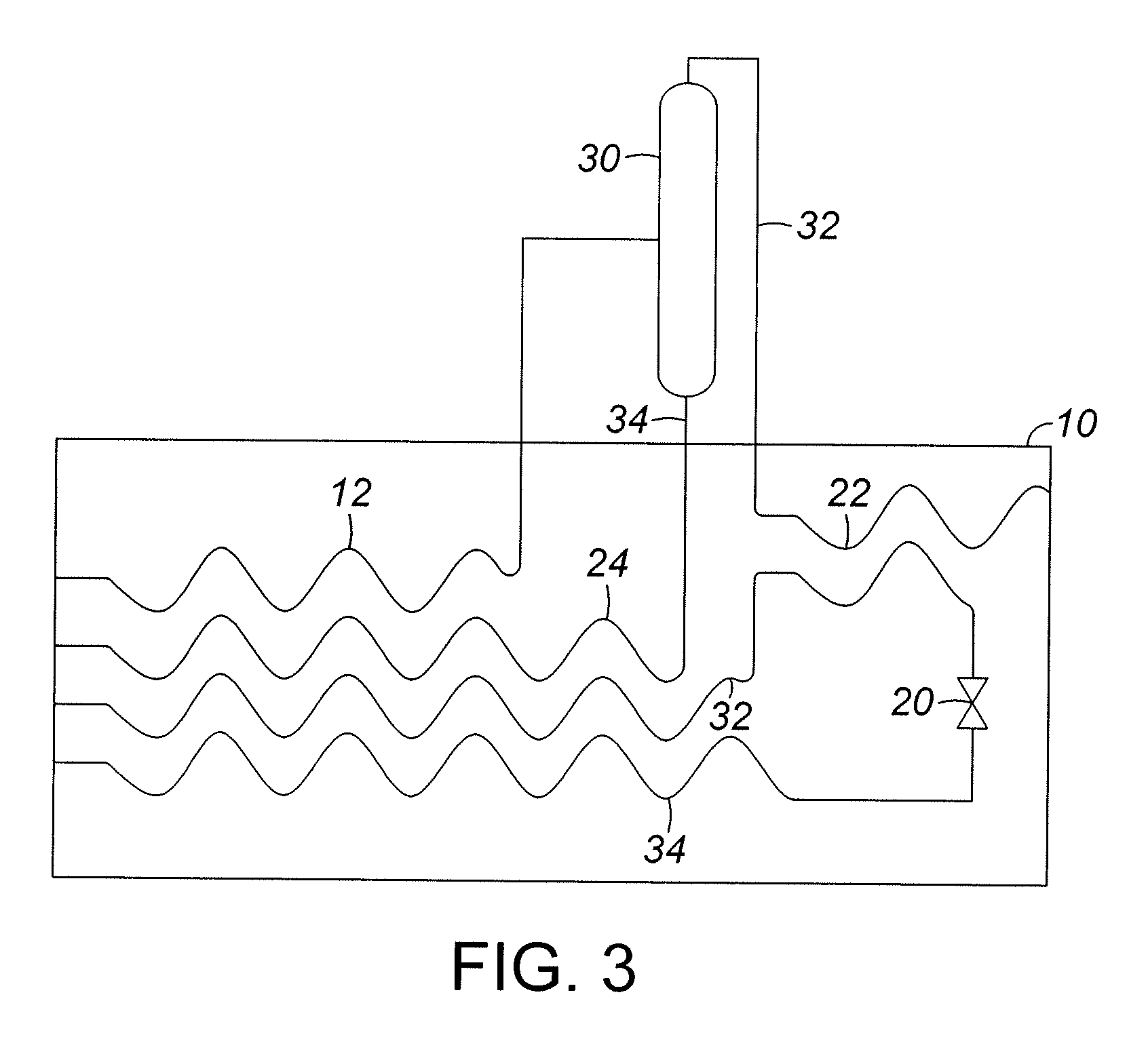
[0005]The use of a compact self-cooling heat exchanger for separating a fluid mixture is disclosed. The heat exchanger is made up of a plurality of plates and each plate has at least two channels defined in the plate. A fluid mixture is passed through a heat exchanger and cooled. The fluid mixture is expanded through a controlled expansion to provide the desired cooling load, and conditions for passing the expanded fluid mixture to a separation unit. The fluid mixture is expanded to create a two phase mixture of liquid and vapor. The two phase mixture is passed to a separation unit, where a first process stream enriched in at least one component is produced, and a second process stream enriched in at least a second component is produced. The first proces

Problems solved by technology

Many areas where natural gas is located are remote in the sense that there are no convenient pipelines to readily transfer the natural gas to.
These shell and tube heat exchangers are very large and very expensive, and present problems of economics and feasibility for remote and smaller natural gas fields.

Method used


Image

  • Separation of a Fluid Mixture Using Self-Cooling of the Mixture
  • Separation of a Fluid Mixture Using Self-Cooling of the Mixture
  • Separation of a Fluid Mixture Using Self-Cooling of the Mixture

Examples


Embodiment Construction

[0010]The use of liquefied natural gas (LNG) is increasing, as fuel and a means of transporting natural gas from remote sites having natural gas, without a nearby gas pipeline, to more distant areas where the natural gas is consumed. Natural gas is typically recovered from gas wells that have been drilled and is in the gas phase at high pressure. The high pressure gas is then treated and passed to a pipeline for transport. However, there are an increasing number of natural gas fields that are in remote locations relative to natural gas pipelines. The present invention is directed to a heat exchanger for cooling the natural gas at the gas wells. By providing an inexpensive heat exchanger for cooling and liquefying natural gas in remote locations, natural gas can be recovered on site and transported as LNG, rather than requiring a natural gas pipeline, or transporting the gas at very high pressures. In addition, improved methods for liquefying natural gas can also lead to improved met...


PUM


Abstract

The use of an inexpensive heat exchanger for self-cooling of a fluid mixture is disclosed. The heat exchanger is made up of a plurality of plates and each plate has at least two channels defined in the plate. A fluid mixture is cooled and expanded, and separated, generating at least two process streams. One or more of the process streams are passed back to the heat exchanger to cool the fluid mixture.

Description

FIELD OF THE INVENTION[0001]The present invention relates to the cooling of fluids through the self-cooling from the fluid. More particularly this invention goes to the cooling of a fluid to self-cool the fluid and to cool and separate the self-cooled fluid.BACKGROUND OF THE INVENTION[0002]The demands for natural gas have increased in recent years. The transport of natural gas is through pipelines or through the transportation on ships. Many areas where natural gas is located are remote in the sense that there are no convenient pipelines to readily transfer the natural gas to. Therefore natural gas is frequently transported by ship. The transport of natural gas on ships requires a means to reduce the volume and one method of reducing the volume is to liquefy the natural gas. The process of liquefaction requires cooling the gas to very low temperatures. There are several known methods of liquefying natural gas as can be found in U.S. Pat. No. 6,367,286; U.S. Pat. No. 6,564,578; U.S. ...

Claims


Application Information

Patent Timeline
IPC IPC(8): F25J3/00
CPCC10L3/10F25J3/0209F25J3/0233F25J3/0238F25J3/061F25J3/0635F25J3/064F25J5/002F25J2200/02F25J2240/30F25J2240/40F25J2270/02F25J2290/42F28D9/00
Inventor DALY, PHILLIP F.VANDEN BUSSCHE, KURT M.
Owner UOP LLC
Learn More