Resistance bridge architecture and method

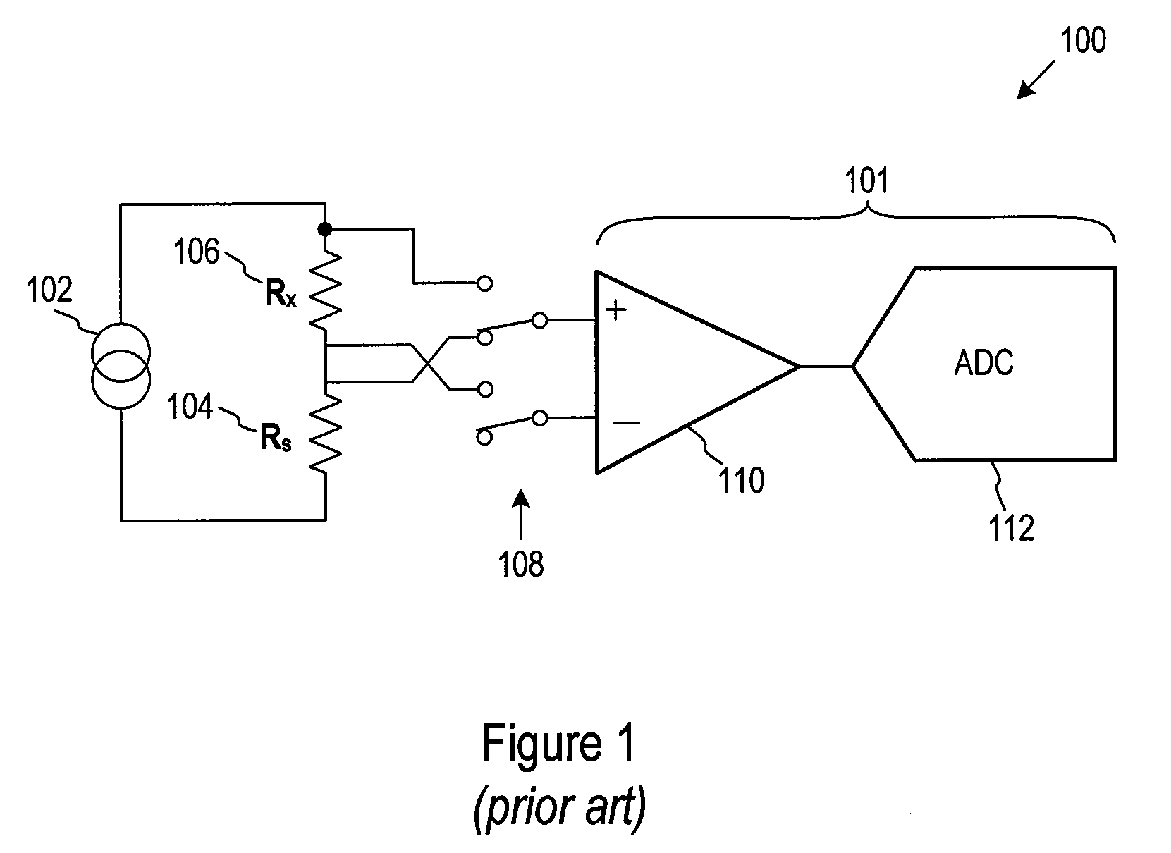
a resistance bridge and bridge technology, applied in the direction of automatic balancing arrangements, instruments, heat measurement, etc., can solve the problems of current drift, limited accuracy of resistance bridge measurement circuit, and drift affecting the accuracy of resistance bridge measuremen

Active Publication Date: 2011-01-06
JOHN FLUKE MFG CO INC
View PDF3 Cites 13 Cited by
  • Summary
  • Abstract
  • Description
  • Claims
  • Application Information

AI Technical Summary

Problems solved by technology

Therefore, the accuracy of a resistance bridge measurement circuit may be limited by the stability of the electrical components within the bridge architecture.
For instance, if drift is present in a current source of a resistance bridge measurement circuit, that drift may affect the accuracy of a m

Method used


Image

  • Resistance bridge architecture and method
  • Resistance bridge architecture and method
  • Resistance bridge architecture and method

Examples


Embodiment Construction

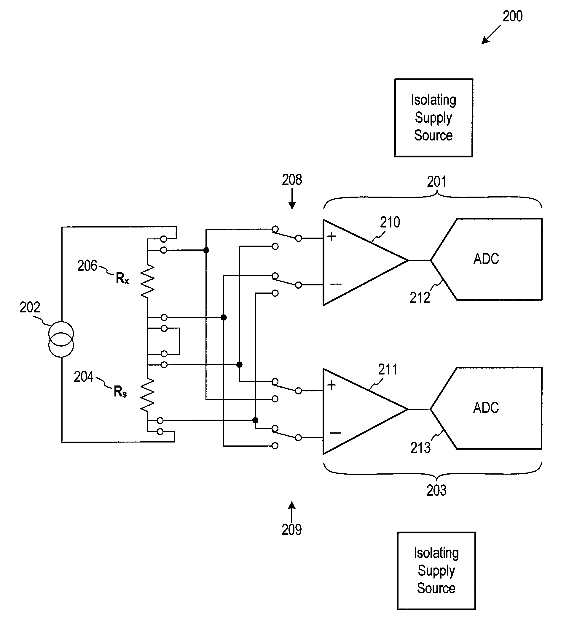
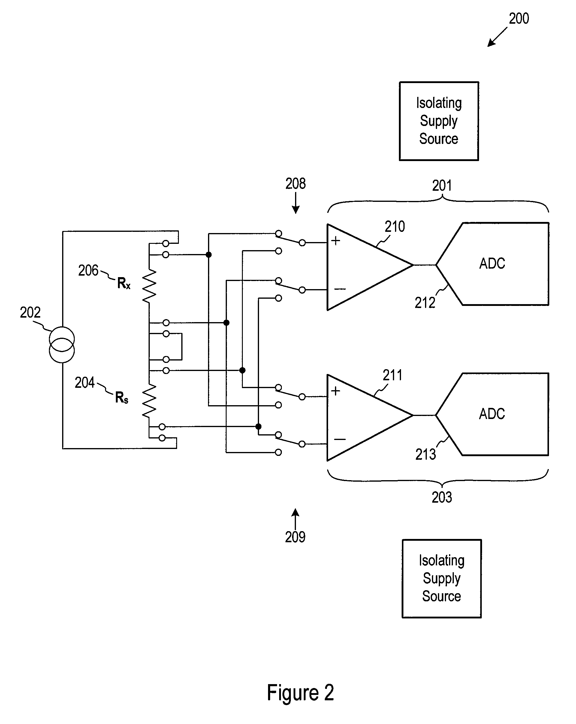
[0010]Embodiments of the present invention are directed toward resistance bridge architectures using two measurement circuits, and more particularly, one or more embodiments are directed to resistance bridge architectures using two measurement circuits in tandem. Certain details are set forth below to provide a sufficient understanding of the invention. However, it will be clear to one skilled in the art that the invention may be practiced without these particular details.

[0011]One or more embodiments utilize a resistance bridge having two voltage measurement circuits that function in tandem to measure a voltage across two resistors. The voltage across each resistor is used to calculate a ratio which may be used to determine a resistance of one of the resistors. For instance, a constant current may be applied to two resistors coupled in series. A first measurement circuit may measure a first voltage across a first resistor, which is a standard resistor with a known resistance. At th...


PUM


Abstract

One or more embodiments are directed to a resistance bridge having two voltage measurements circuits that function in tandem. In one embodiment, a constant current source may be applied to two resistors coupled in series, in which the first resistor has a known resistance and the second resistor has a resistance to be determined or verified. A first measurement circuit may measure a first voltage across the first resistor and at substantially the same time a second measurement circuit measures a second voltage across the second resistor. The voltage of each resistor is converted to a ratio. Based on the ratio and the resistance of the first resistance, the resistance of the second resistor may be calculated.

Description

TECHNICAL FIELD[0001]This invention is directed to resistance bridge architecture, and more particularly one or more embodiments are directed to resistance bridge architecture using two measurement circuits.BACKGROUND OF THE INVENTION[0002]A resistance bridge is a device for comparing resistors by measuring a ratio between resistors. For instance, a resistance bridge may be used to determine a resistance value of a first resistor that is electrically coupled to a second resistor. The resistance bridge measures electrical parameters of the two resistors, and, based on the electrical measurements, a microprocessor coupled to the resistance bridge calculates a ratio of the two resistors. Resistance bridges may be used in a wide variety of applications that use resistance measurements, such as thermometers, resistor calibrators, multimeters and the like. In general, resistance bridge measurement circuits provide high accuracy measurements. However, the accuracy of any circuit depends on...

Claims


Application Information

Patent Timeline
IPC IPC(8): G01R27/08
CPCG01K7/20G01R17/02G01K15/00
Inventor WALKER, RICHARD W.
Owner JOHN FLUKE MFG CO INC
Why Eureka
Try Eureka