Solar collector

a solar collector and solar panel technology, applied in the field of solar panels, can solve the problems of increasing the possibility of compromising and achieve the effect of improving the structural integrity of the sam

Inactive Publication Date: 2011-01-13
E CUBE ENERGY TECH CO LTD
View PDF7 Cites 9 Cited by
  • Summary
  • Abstract
  • Description
  • Claims
  • Application Information

AI Technical Summary

Problems solved by technology

As the arrays increase in size, however, the potential for the structural integrity of the same to be compromised increases.

Method used


Image

  • Solar collector
  • Solar collector
  • Solar collector

Examples


Embodiment Construction

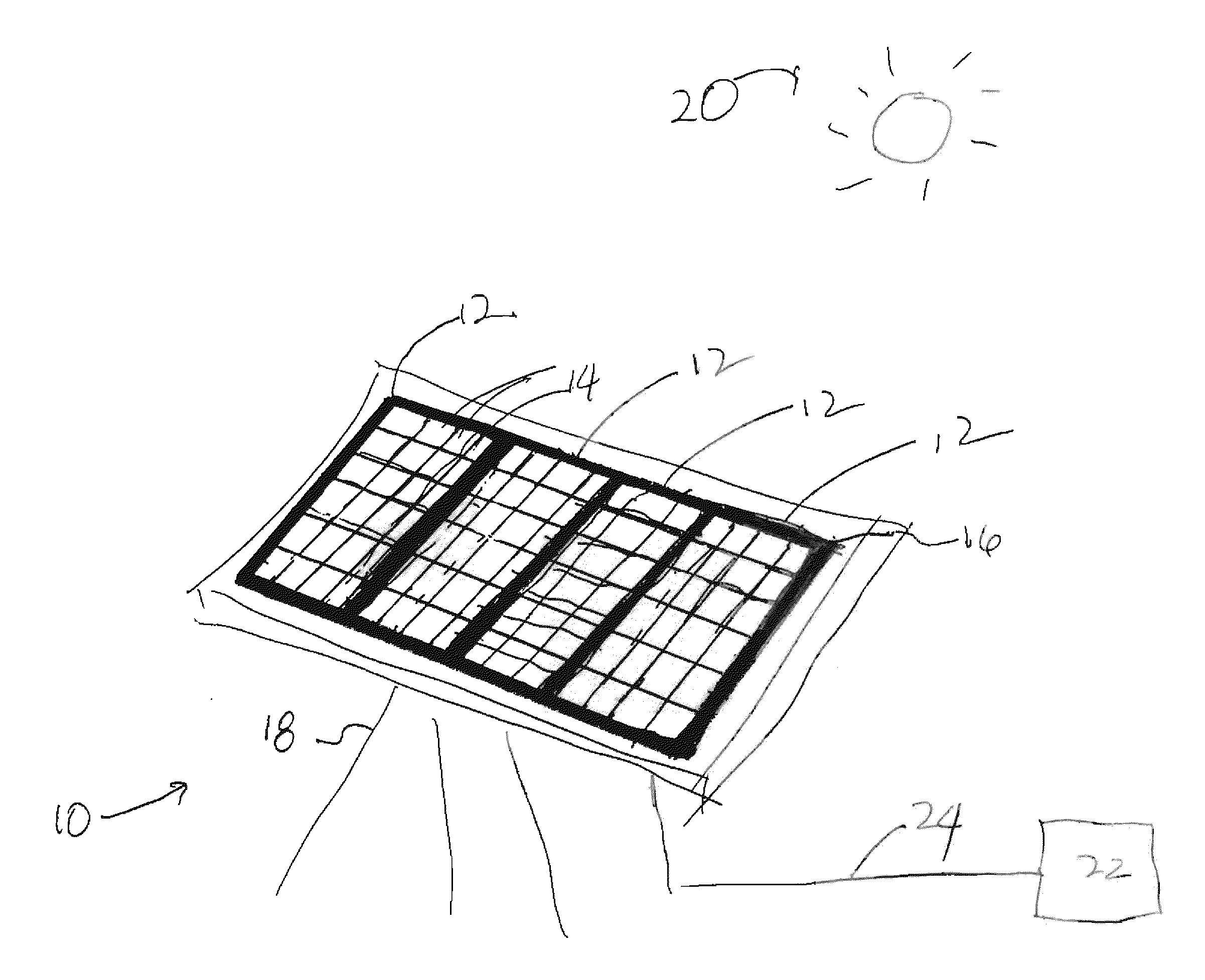
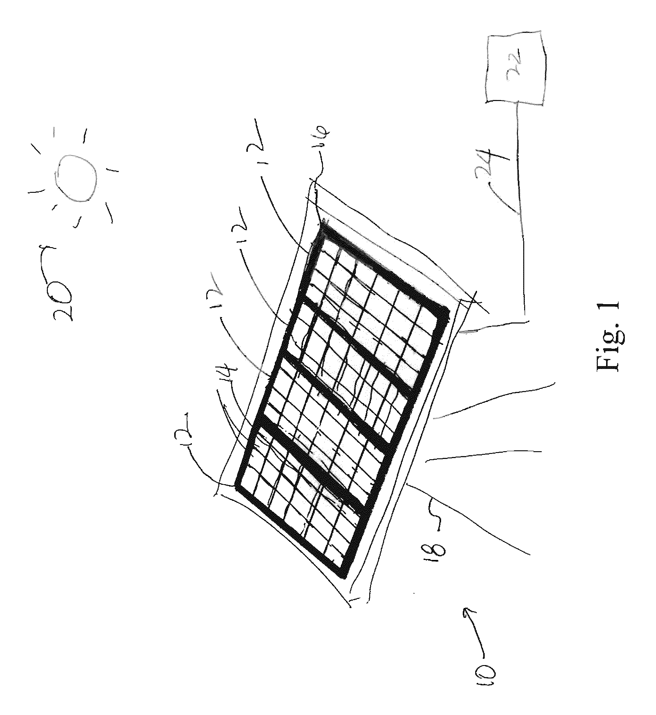
[0013]Referring to FIG. 1 a solar collector 10 includes multiple arrays 12 of solar cells 14. Collector 10 includes a frame 16 that is disposed on a stand 18 and holds multiple arrays 12 together. Typically, array 12 is disposed so as to allow the sun 20 to impinge upon solar cells 14. The energy collected may then be transported to a desired system 22 using suitable conduits 24 coupled between array 12 and system 22. Were solar collector 10 employed to generate thermal energy, conduits would be pipes through which a fluid passed and system would be a suitable device to use the heat fluid, e.g., a hot water storage container. In the case of a generation of electrical energy, conduits 24 would be electrical wires and system 22 may be any suitable electrical storage device. For purposes of the present discussion, solar collector 10 is described as being employed to generate electrical energy.

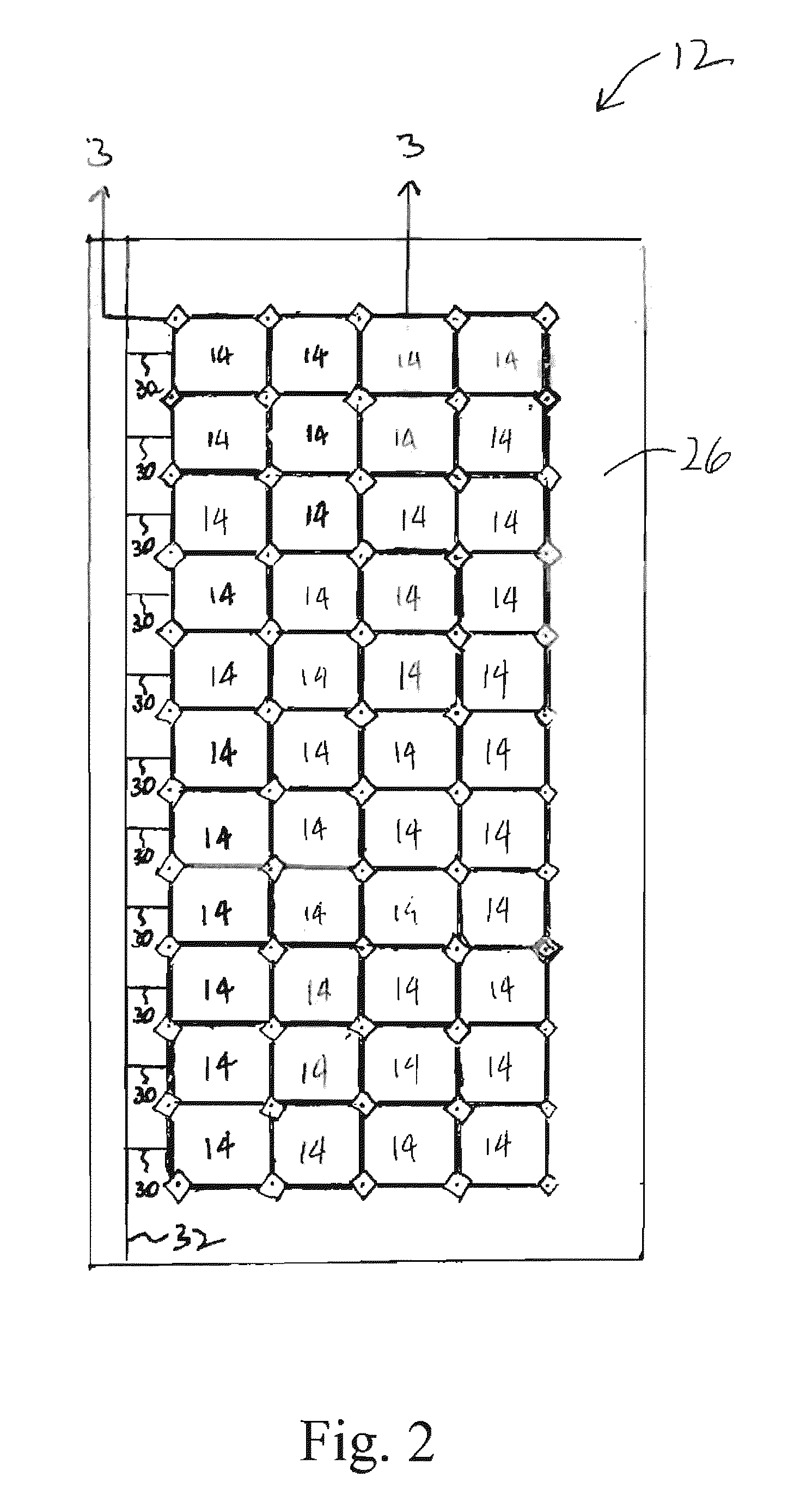
[0014]Referring to both FIGS. 1 and 2, each array 12 includes multiple photovoltaic solar cell...


PUM


Abstract

A solar collector comprising an array of solar cells, each of which is spaced-apart from a subset of solar cells adjacent thereto, defining a hiatus therebetween; a first substrate disposed to cover the array of solar cells; and a second substrate disposed to cover the array of solar cells, with the array begin position between the first and second substrates, with a plurality of throughways, each of which extends from an aperture in the first substrate, traversing the hiatus and terminating in an opening in the second substrate.

Description

BACKGROUND OF THE INVENTION[0001]The present invention generally relates to solar panels and more particularly to a solar collector exposed to fluid streams.[0002]Solar power has been viewed by many as a highly desirable energy resource, because it may be readily used to generate thermal and electrical energy. For example, a solar collector may collect thermal energy from the sun and direct the same to a desired system to increase the thermal energy of a component thereof, e.g., such as fluids that may include water, oil and the like. A solar collector employing a transducer, such as a photovoltaic device, may convert energy from the sun into electricity. By arranging solar collectors in arrays, power plants have been developed that generate vast amounts of electricity.[0003]As the arrays increase in size, however, the potential for the structural integrity of the same to be compromised increases. This may be a function of both the materials from which the array is fabricated, as we...

Claims


Application Information

Patent Timeline
Patent Type & Authority Applications(United States)
IPC IPC(8): F24J2/46
CPCF24J2/20F24J2/4638F24J2002/4603Y02E10/50H01L31/048Y02E10/44H01L31/042F24S10/50F24S40/85F24S2080/05
Inventor XIANG, XIAO-DONGZHANG, RONG
Owner E CUBE ENERGY TECH CO LTD
Why Eureka
Try Eureka