
Adjustable Spring Assist for Window Coverings and Awnings

a technology of spring assist and window covering, which is applied in the direction of door/window protective devices, light protection screens, doors/windows, etc., can solve the problems of requiring larger roller tubes, and requiring more electric energy to operate, so as to reduce the weight of the blind, and easy to match

Inactive Publication Date: 2011-01-13
NG PHILIP
View PDF0 Cites 52 Cited by
  • Summary
  • Abstract
  • Description
  • Claims
  • Application Information

AI Technical Summary

Benefits of technology

[0004]In accordance with one aspect of the present invention, there is provided a spring assisted lifting mechanism for lifting and lowering a blind which permits the quick and easy matching of the spring assist pre-rotation to the drive mechanism for lifting and lowering the blind. The device includes an elongated cylinder coupled to the blind such that rotating the cylinder about its axis lifts and lowers the blind. Coupled to the elongated cylinder is a cylinder drive which is configured to rotate the elongated cylinder about its axis. A torsion spring is coupled to the cylinder for biasing the elongated cylinder to at least partially neutralize the weight of the blind. The torsion spring is in turn coupled to a spring preload adjuster which is configured to adjust the tension on the torsion spring by moving an adjustment member. The spring preload adjuster is further configured such that the adjustment member extends perpendicularly away from the axis of the elongated cylinder.

Problems solved by technology

Firstly, they are generally larger and therefore require larger roller tubes.
Also, they tend to be more expensive, and most significantly, they require more electric energy to operate.
Combining an electric motor with a spring assist is not practical because it is very difficult to match the required pre-rotation of the spring assist when the spring assist is coupled to both the roller tube and the electric motor.
If not enough pre-rotation is applied to the spring assist, then the electric motor will either not be able to operate the blind or the motor will draw too much current and potentially burn out.
However, if too much pre-rotation is applied to the spring assist, then the electric motor will not be able to fully lower a raised roller blind, or in the case of roman, pleated or cellular blinds, the electric motor will not be able to fully raise the blind.
Unfortunately, the only way to correctly preset the pre-rotation of the spring assist to match with the electric motor would be to repeatedly preset the spring assist pre-rotation, then assemble and mount the blind, then test the pre-rotation of the spring assist, then take down the blind again, disassemble it and reset the pre-rotation of the spring assist.
As a result, spring assisted electrically driven blinds have not been available in the market.

Method used


Image

  • Adjustable Spring Assist for Window Coverings and Awnings
  • Adjustable Spring Assist for Window Coverings and Awnings
  • Adjustable Spring Assist for Window Coverings and Awnings

Examples


Embodiment Construction

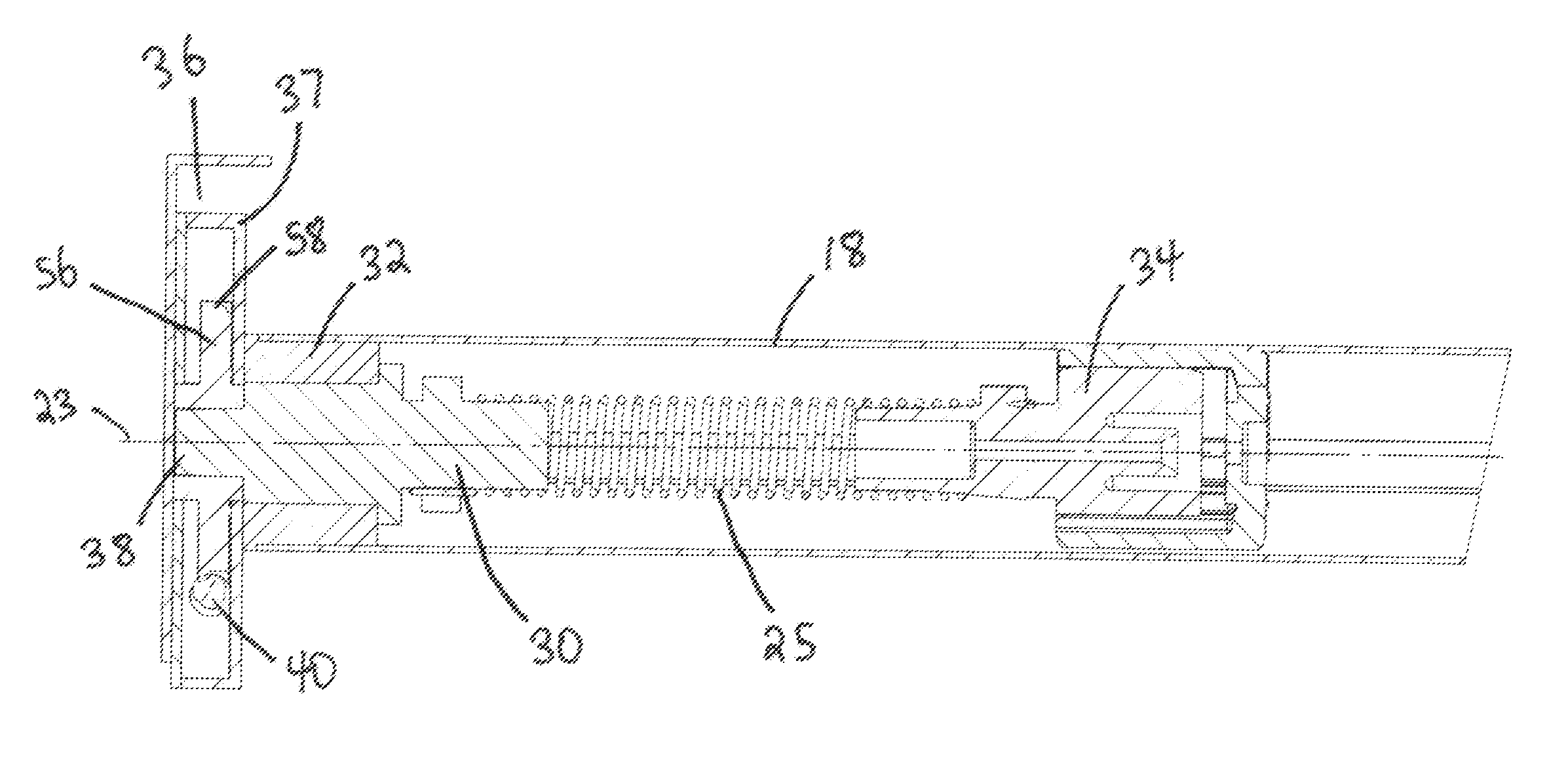
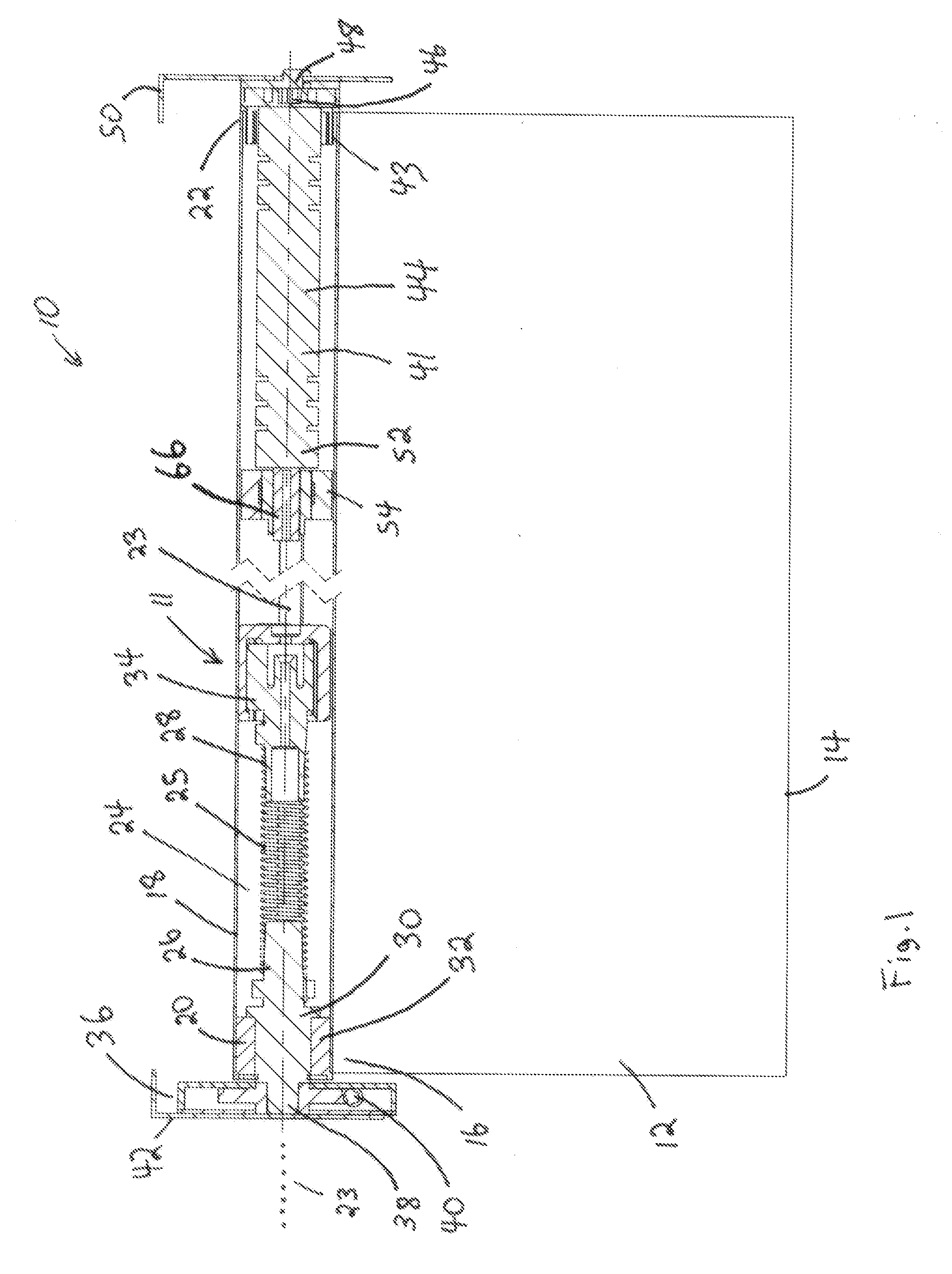
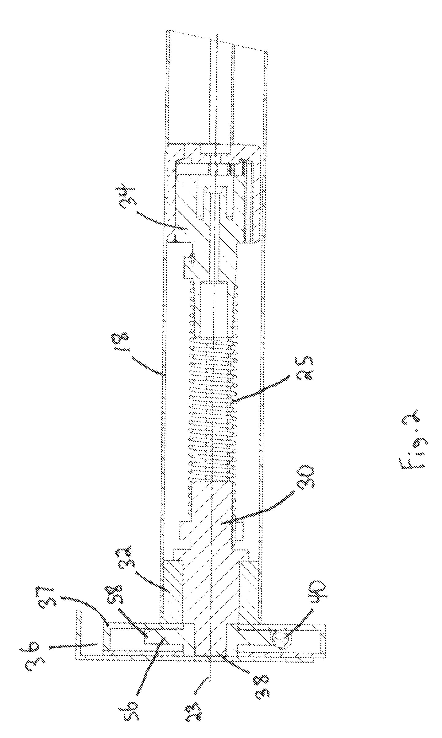
[0017]Referring firstly to FIG. 1, a blind incorporating an adjustable spring assisted blind lifting device made in accordance with the present invention is shown generally as item 10 and includes blind 12 having lower end 14 and upper end 16. Upper end 16 is attached to drive mechanism 11 which includes elongated cylinder 18 having opposite ends 20 and 22 and axis 23. Elongated cylinder 18 is preferably an elongated tube of the type generally used to construct roller blinds (often called roller tubes). Attached to end 20 of elongated cylinder (roller tube) 18 is spring assist mechanism 24 which consists of an elongated torsion spring 25 having opposite ends 26 and 28. Spring assist mechanism 24 is configured to apply a biasing torque to elongated cylinder (roller tube) 18 to at least partially neutralize the weight of blind 12. End 26 of torsion spring 26 is attached to coupling 30 which is in turn rotatably coupled to yoke 32 which is coupled to end 20 of roller tube 18. Opposite ...


PUM


Abstract

There is provided a spring assisted electric motor driven lifting mechanism for lifting and lowering a blind which permits the quick and easy matching of the spring assist pre-rotation to the torque output of the electric motor. The device includes an elongated cylinder coupled to the blind such that rotating the cylinder about its axis lifts and lowers the blind. Coupled to the elongated cylinder is an electric motor which is configured to rotate the elongated cylinder about its axis. A torsion spring is coupled to the cylinder for biasing the elongated cylinder to at least partially neutralize the weight of the blind. The torsion spring is in turn coupled to a spring preload adjuster which is configured to adjust the tension on the torsion spring by moving an adjustment member. The spring preload adjuster is further configured such that the adjustment member extends perpendicularly away from the axis of the elongated cylinder.

Description

FIELD OF THE INVENTION[0001]The invention relates generally to adjustable spring assist mechanisms which are used in window coverings and awnings to partially neutralize the weight of the blind or awning.BACKGROUND OF THE INVENTION[0002]Motorized blinds incorporate an electric motor to raise and lower the blind. These motorized blinds usually incorporate an elongated roller tube upon which either the blind (in the case of a roller blind) or the support chords (in the case of a roman, pleated, cellular or other blind) are wound. The electric motor is placed within the roller tube and, upon activation, causes the roller tube to rotate about its axis, either lifting or lowering the blind. The electric motor must be sufficiently large to apply sufficient torque to the roller tube to overcome the weight of the blind when the blind is fully lowered (in the case of a roller blind) or when the blind is fully raised (in the case of a roman, pleated or cellular blind). For a standard sized bl...

Claims


Application Information

Patent Timeline
Patent Type & Authority Applications(United States)
IPC IPC(8): E06B9/68E06B9/60
CPCE06B9/60E06B9/44
Inventor NG, PHILIP
Owner NG PHILIP
Features
  • Generate Ideas
  • Intellectual Property
  • Life Sciences
  • Materials
  • Tech Scout
  • Unparalleled Data Quality
  • Higher Quality Content
  • 60% Fewer Hallucinations
Learn More