

Electric toothbrush
a toothbrush and electric technology, applied in the field of electric toothbrushes, can solve the problems of difficult to obtain high detection precision and easy downsizing of the motor
- Summary
- Abstract
- Description
- Claims
- Application Information
AI Technical Summary
Benefits of technology
Problems solved by technology
Method used
Image

Examples
first embodiment
Configuration of Electric Toothbrush
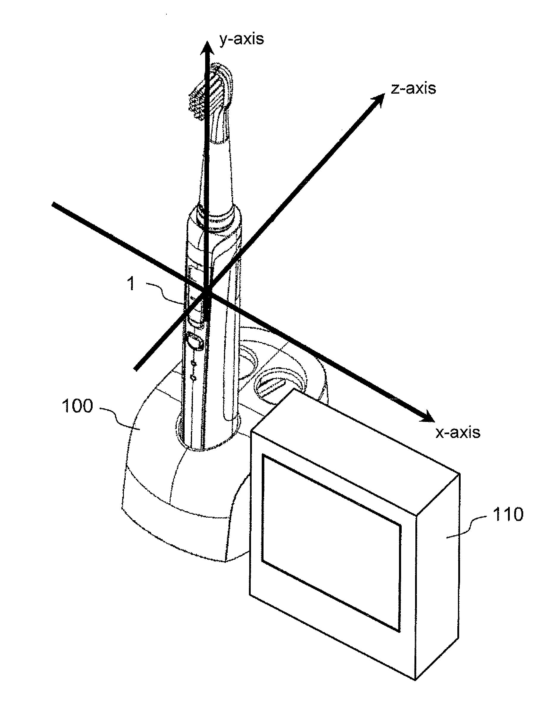
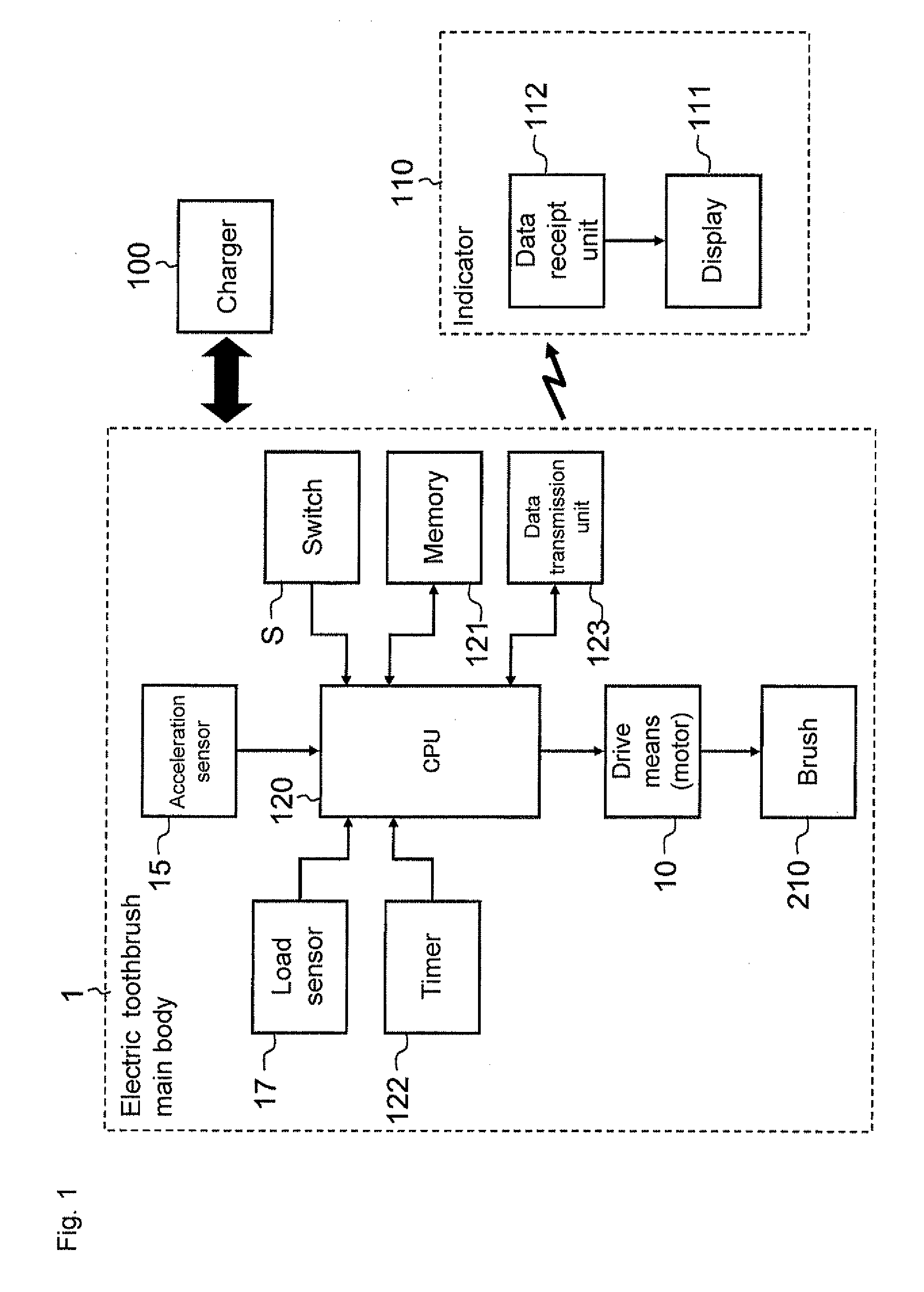
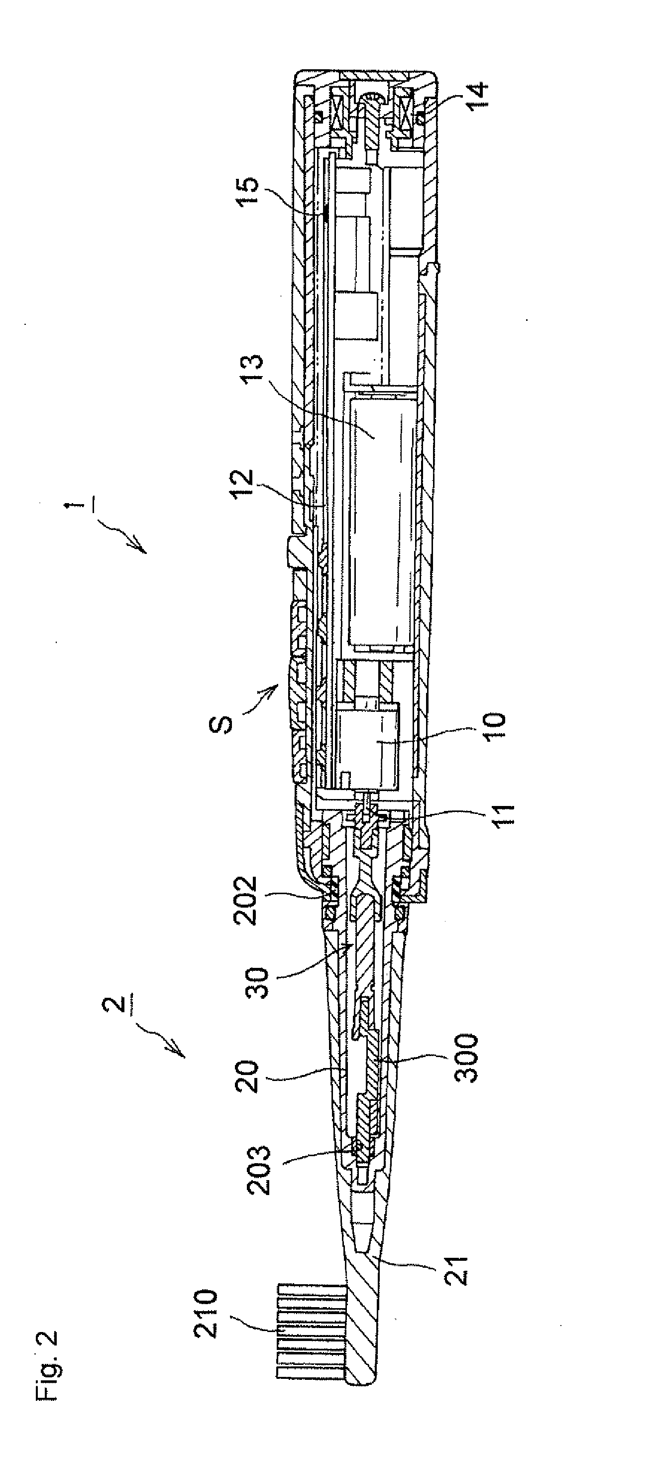
[0071]With reference to FIGS. 1, 2 and 3, a configuration of an electric toothbrush will be described. FIG. 1 is a block diagram of an electric toothbrush of a first embodiment, FIG. 2 is a sectional view showing an internal configuration of the electric toothbrush of the first embodiment, and FIG. 3 is a perspective view showing an outer appearance of the electric toothbrush.
[0072]The electric toothbrush is provided with an electric toothbrush main body 1 (hereinafter, also simply referred to as the “main body 1”) in which a motor 10 serving as a drive source is built, a vibration member 2 having a brush 210. The main body 1 has a substantially cylindrical shape and also serves as a handle portion to be gripped by a user by hand at the time of brushing teeth. Further, the electric toothbrush of the present embodiment is provided with a charger 100 for resting and charging the main body 1, and an indicator 110 for outputting a brushing result.
[007...
second embodiment
[0121]FIG. 18 is a flowchart of a brushing evaluation process of a second embodiment. The brushing result is outputted after completion of brushing in the first embodiment, whereas interim results are outputted in the middle of brushing in the second embodiment (S55). Other configurations are the same as the first embodiment.
[0122]According to processes of the present embodiment, brushing can be performed while confirming progress of the brushing time and the brushing barometer (the achievement degree) in real-time. Thus, convenience is improved. By confirming the evaluation results of the brush angle and the brush pressure, the user can determine whether or not the brush angle and the brush pressure are proper. In the second embodiment, a function of outputting the interim result of the brush angle corresponds to brush angle guide means of the present invention.
third embodiment
[0123]FIG. 19 is a flowchart of a brush angle estimation process (S40 of FIG. 5) of a third embodiment. In the present embodiment, the CPU 120 estimates the brush angle, and then, if necessary, outputs a guide for informing the user of whether or not the brush angle is proper.
[0124]The CPU 120 firstly estimates the brush angle based on a posture vector A obtained from the acceleration sensor (particularly the acceleration component Az in the z direction) (S1900). The CPU 120 updates the value of the brush angle for the current brushing part estimated in S20 (S1901). At this time, the CPU 120 preferably calculates and records the average value of the brush angle from the value of the brush angle stored in the memory and an estimated value this time.
[0125]Next, the CPU 120 compares the estimated value of the brush angle and the optimum value of the brush angle in the current brushing part (S1902). For example, given that the optimum value of the brush angle is “35 to 55°”, in a case w...
PUM
 Abstract
Description
Claims
Application Information