Screw rotor

a screw rotor and rotor shaft technology, applied in the direction of liquid fuel engines, machines/engines, combination engines, etc., can solve the problems of reducing sealing performance, affecting the rotational balance of the screw rotor, and inefficient pumping operation of the screw pump

Inactive Publication Date: 2011-01-27
TOYOTA IND CORP
View PDF3 Cites 10 Cited by
  • Summary
  • Abstract
  • Description
  • Claims
  • Application Information

AI Technical Summary

Problems solved by technology

However, the number of turns is less on the suction side of the screw rotor with large lead angle, which affects rotational balance of the screw rotor.
In such a case, sealing length between the inner surface of the rotor housing and the to

Method used


Image

  • Screw rotor
  • Screw rotor
  • Screw rotor

Examples


second embodiment

[0023]FIG. 12 schematically shows tooth profiles of the first and second screw rotors according to the present invention.

DETAILED DESCRIPTION OF THE PREFERRED EMBODIMENTS

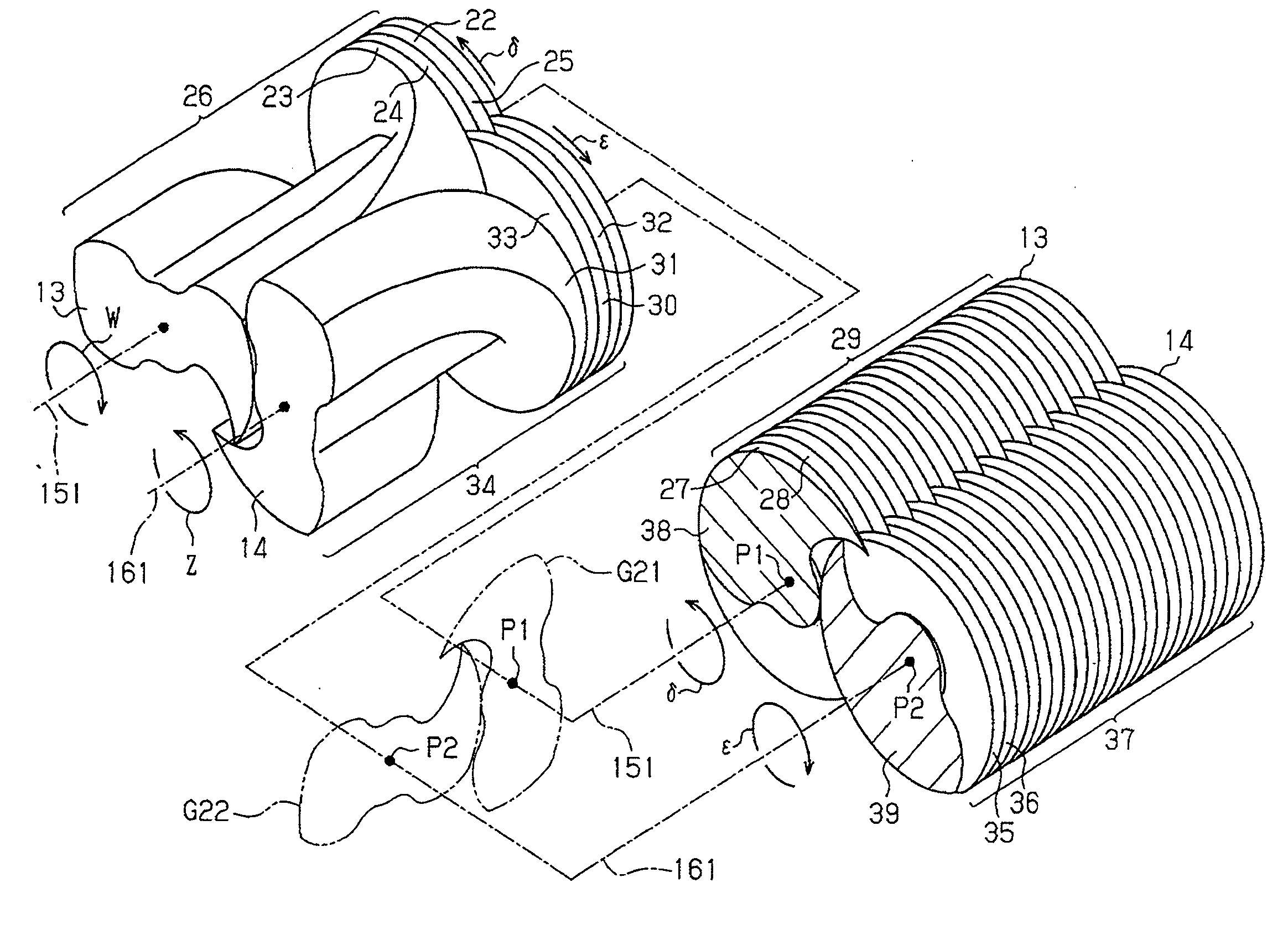
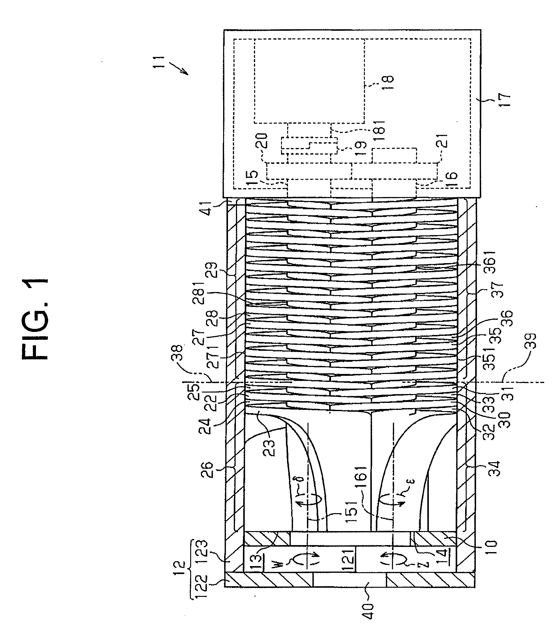
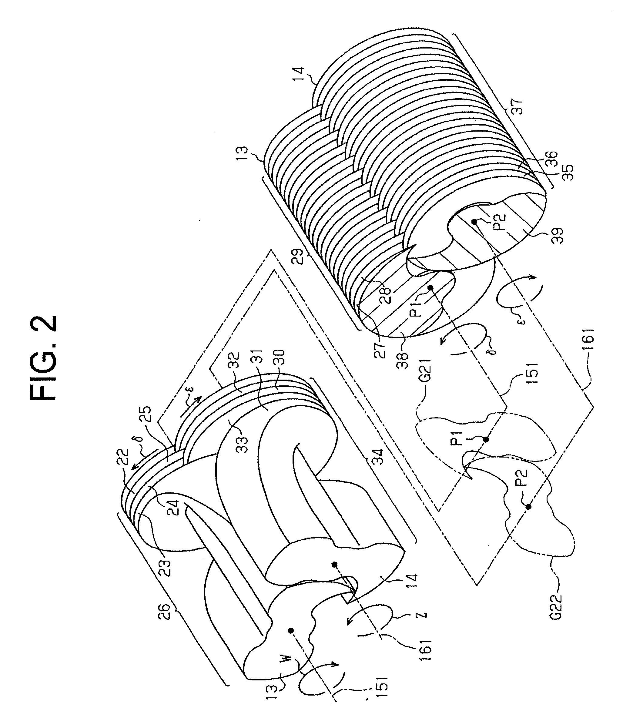
[0024]Referring to FIG. 1, a screw pump 11 has a rotor housing 12 in which a first screw rotor 13 and a second screw rotor 14 are provided rotatably. The shaft 15 of the first screw rotor 13 and the shaft 16 of the second screw rotor 14 extend into a motor housing 17 of the screw pump 11 where an electric motor 18 is accommodated. Driving force generated by the electric motor 18 is transmitted through its output shaft 181 and the coupling 19 to the shaft 15, thus rotating the shaft 15. The rotating motion of the shaft 15 is transmitted to the other shaft 16 through a pair of gears 20 and 21 engaged with each other, so that the shaft 16 is rotated in the direction opposite to the shaft 15. The first screw rotor 13 is rotated in the direction indicated by arrow W, and the second screw rotor 14 is rotated in the direct...

first embodiment

[0086]The first and second screw rotors 13, 14 offer the following advantages.

[0087](1) The first curved portions A1C1, A2C2 satisfy the condition (1) or (2). Accordingly, when the first and second screw rotors 13, 14 are rotated two complete turns from the angular position of 0 degree (0 to 720 degree), the fluid transfer volume (V1+V2) indicated by the curve HQ in FIG. 10 converges to the maximum volume Vq on the curve Q without increasing. That is, when the first and second screw rotors 13, 14 are rotated two complete turns from the angular position of 0 degree (0 to 720 degree), the volume of the helical grooves adjacent to the boundary planes 38, 39 converges to the maximum volume Vq on the curve Q without increasing. This contributes to preventing inefficient pumping operation of the screw pump 11 while maintaining a good rotational balance of the screw rotors 13, 14 and ensuring sealing performance.

[0088](2) When dimensional error of the tooth profiles G11, G12, G21, G22 is ...


PUM


Abstract

A screw rotor is for use in a screw pump that pumps fluid by rotation of a pair of screw rotors engaged with each other in a rotor housing. The screw rotor includes a multiple-thread portion for pump suction side and a single-thread portion for pump discharge side. The screw rotor is formed so that the tooth profile of the multiple-thread portion is connected to the tooth profile of the single-thread portion through a boundary plane that is perpendicular to the rotation axis of the screw rotor. The first curved portion coincides with the third curved portion in the boundary plane.

Description

BACKGROUND OF THE INVENTION[0001]The present invention relates to a screw rotor for use in a screw pump that pumps fluid by rotation of a pair of screw rotors engaged with each other in the screw pump.[0002]Japanese Unexamined Patent Application Publication No. 2008-38861discloses a screw pump having a pair of single-thread screw rotors engaged with each other. The lead angle of the screw rotor on the suction side of the pump is larger than that on the discharge side of the pump, which is suitable for fluid transfer with increased amount of suction. However, the number of turns is less on the suction side of the screw rotor with large lead angle, which affects rotational balance of the screw rotor.[0003]Japanese Examined Patent Application Publication No. 63-59031discloses another screw pump having a pair of multiple-thread screw rotors engaged with each other. In such screw pump, the problem with rotational balance, as in the case of the single-thread screw rotor, does not occur.[0...

Claims


Application Information

Patent Timeline
IPC IPC(8): F04C3/04
CPCF04C2/123F04C14/02F04C11/005F04C2/16
Inventor IZAWA, YUYAYAMAMOTO, SHINYAINAGAKI, MASAHIROYOSHIKAWA, MAKOTO
Owner TOYOTA IND CORP
Why Eureka
Try Eureka