
Dynamic Motile Medium

a dynamic and motile medium technology, applied in the field of light modulating devices, can solve the problems of limiting the capabilities of this device, affecting the speed of the device, and costing to incorporate color into the resulting media

Inactive Publication Date: 2011-02-03
MILES MARK W
View PDF22 Cites 2 Cited by
  • Summary
  • Abstract
  • Description
  • Claims
  • Application Information

AI Technical Summary

Problems solved by technology

Additionally, it is costly to incorporate color into the resulting media since this generally requires the addition of a costly color films.
Speed is also an issue, for the aforementioned reasons.
High voltages of 80V-150V, due to the required large dimensions between electrodes, and costly color also constrain the capabilities of this device.
Particles which are brought into contact with the walls can spoil or degrade the TIR, thus reducing reflectivity significantly and the overall reflection of the structure.
This approach, while offering the prospect of very high inherent reflectivities, does not incorporate a means for color selection.
The design is further complicated by the tradeoff between positioning of the drive electrodes which could either degrade reflectivity (if located on the walls) or increase voltage (if located on the incident plane of the corner cube).

Method used


Image

  • Dynamic Motile Medium
  • Dynamic Motile Medium
  • Dynamic Motile Medium

Examples


Embodiment Construction

In the following description, for purposes of explanation, numerous specific details are set forth in order to provide a thorough understanding of the invention. It will be apparent, however, to one skilled in the art that the invention can be practiced without these specific details. In other instances, structures and devices are shown in block diagram form only in order to avoid obscuring the invention.

Reference in this specification to “one embodiment” or “an embodiment” means that a particular feature, structure, or characteristic described in connection with the embodiment is included in at least one embodiment of the invention. The appearances of the phrase “in one embodiment” in various places in the specification are not necessarily all referring to the same embodiment, nor are separate or alternative embodiments mutually exclusive of other embodiments. Moreover, various features are described which may be exhibited by some embodiments and not by others. Similarly, various r...


PUM


Abstract

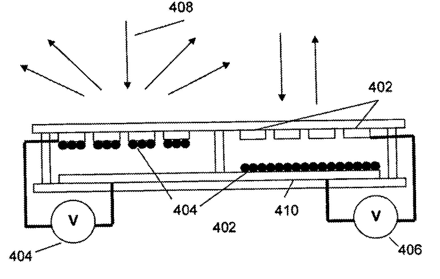
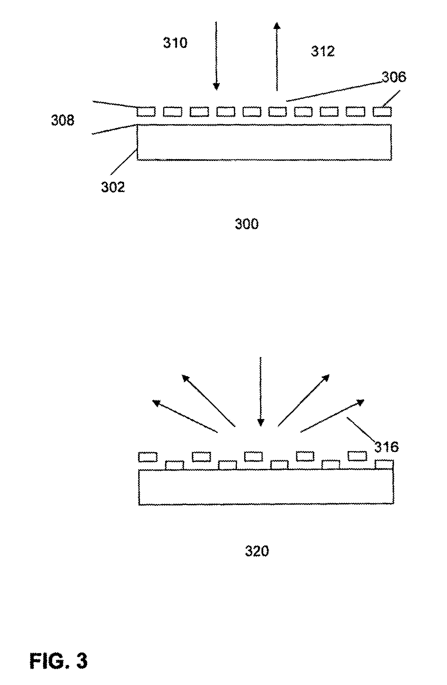
In one embodiment of the invention there is provided a device for modulating light. The device comprises a plurality of nano-scale particles; a conformal structure defining a surface to which the nano-scale particles conform under influence of a displacement force; and a displacement mechanism to apply the displacement force to the nano-scale particles; wherein the nano-scale particles when they conform to the conformal structure change the optical characteristics of the conformal structure.

Description

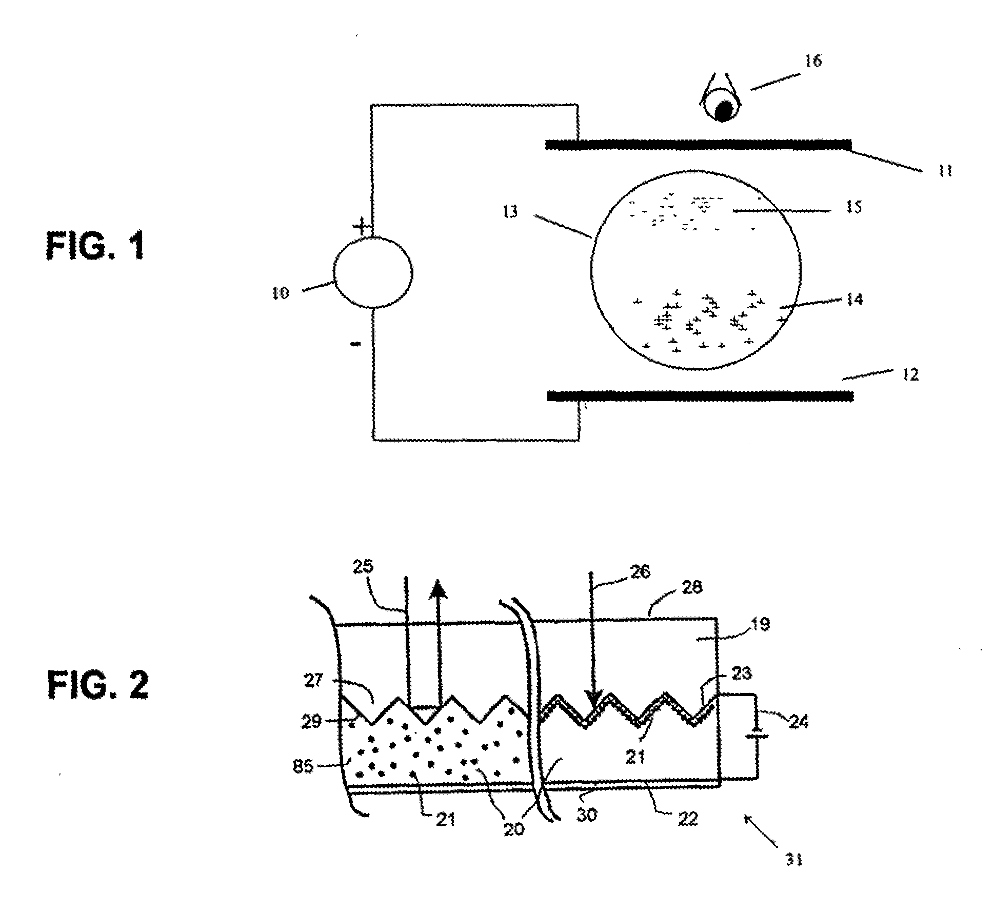
FIELDEmbodiments of this invention relate to light modulating devices in general, and in particular to light modulating devices that operate on the principles of diffraction and / or interference, and may be classified as transmissive or reflective devices.BACKGROUNDElectrophoretic devices such as those illustrated in U.S. Pat. No. 6,392,785fall into the class of microencapsulated displacement types, and spinning or re-orientation types. In the former, charged submicroscopic particles contained within fluid filled transparent micro-shells, can be physically displaced under the influence of an electrical field. Depending on the color of the fluid and the color of the particles, a viewer looking at a sheet containing a dense array of such microshells will see a change in brightness from a dark state to a light state. In the latter, a permanent bipolar charge placed on microscopic sphere can be rotated under the influence of an applied field. If one side of the particle is black and the ...

Claims


Application Information

Patent Timeline
IPC IPC(8): G02F1/167
CPCG02B5/06G02B26/004G02B5/1861B82Y15/00G02B26/00
Inventor MILES, MARK W.
Owner MILES MARK W
Learn More