Dynamic Rowing Machine

a rowing machine and dynamic technology, applied in the field of rowing machines, can solve the problems of occupying more space when in use, potentially detrimental to the rower, and complex and costly rowing machines that simulate oars

Inactive Publication Date: 2011-02-03
ROACH MATTHEW D
View PDF15 Cites 66 Cited by
  • Summary
  • Abstract
  • Description
  • Claims
  • Application Information

AI Technical Summary

Problems solved by technology

These rowing machines that simulate oars are generally more complex and costly than stationary rowing machines, and occupy more space when in use.
However, these known stationary rowing machines are acknowledged by health professionals as being potentially detrimental to the rower, by increasing the likelihood of injury to the rower's knee, back and shoulders due to the increased loading on the body.
Another disadvantage is that they cause rowers to develop improper coordination patterns.
The disadvantage of the prior art stationary machine being mounted on sliding tracks to convert to a dynamic rowing simulator, is that the substantial length of floorspace area it uses and the risk to the rower getting on and off the machine, and to others in close proximity of the moving tracks at floor level.
The sliding tracks also make it difficult / practical to maintain the hygiene of the floorspace below the machine after active use of the machine, particularly important in public gyms and rowing clubs.
The space required to connect these machines in a room is significant.
This is a disadvantage, as to correctly simulate the biodynamics of the rower's leg drive during the rowing stroke it is preferable that the rower's feet be positioned closer together, than can be achieved with his feet on either side of a monorail beam, as is the case with the Concept 2 machines.

Method used


Image

  • Dynamic Rowing Machine
  • Dynamic Rowing Machine
  • Dynamic Rowing Machine

Examples


Embodiment Construction

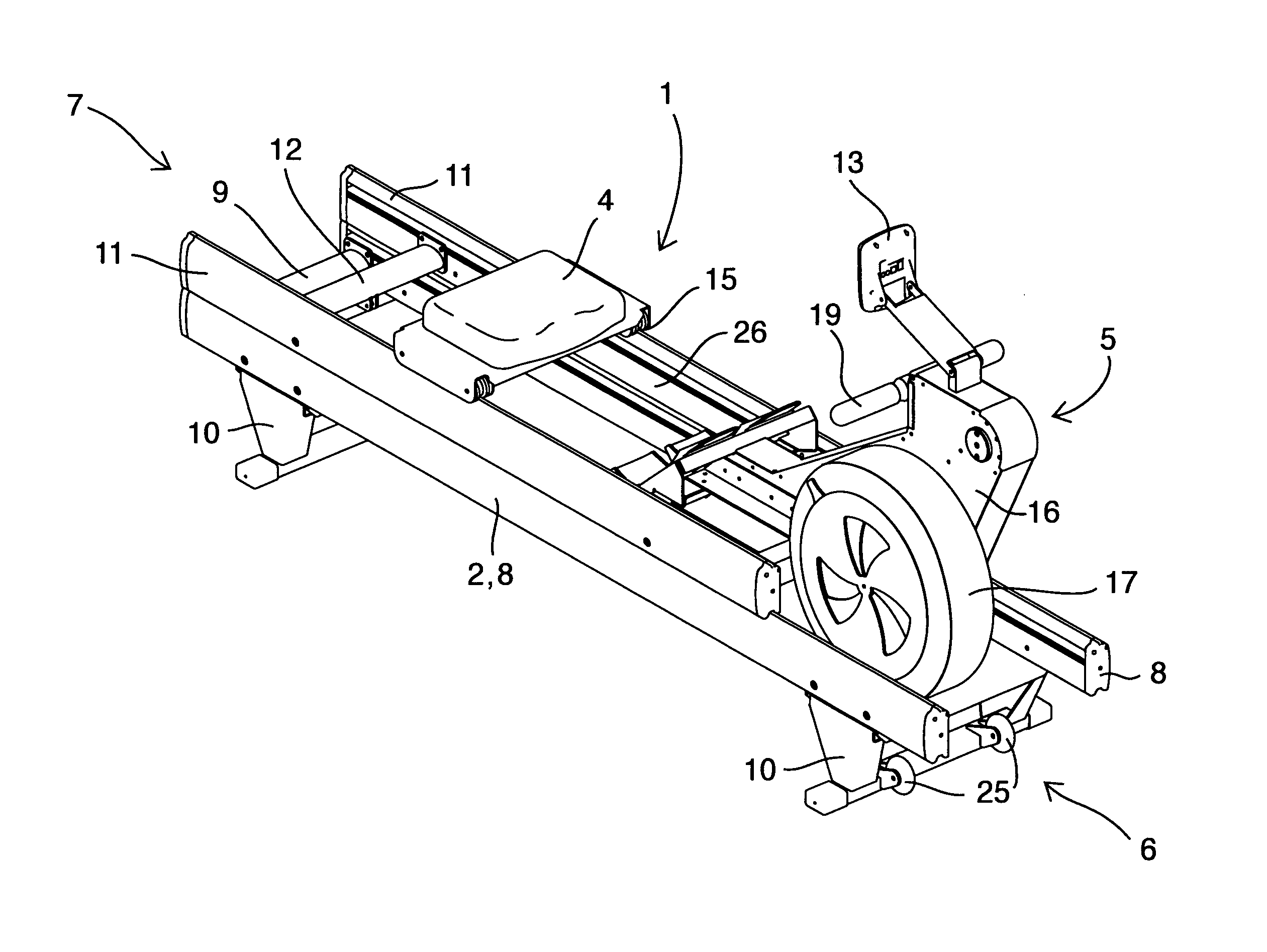
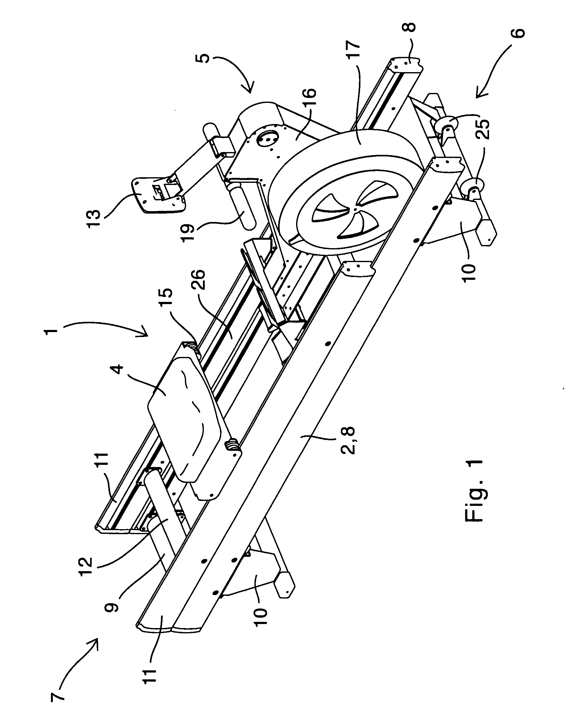
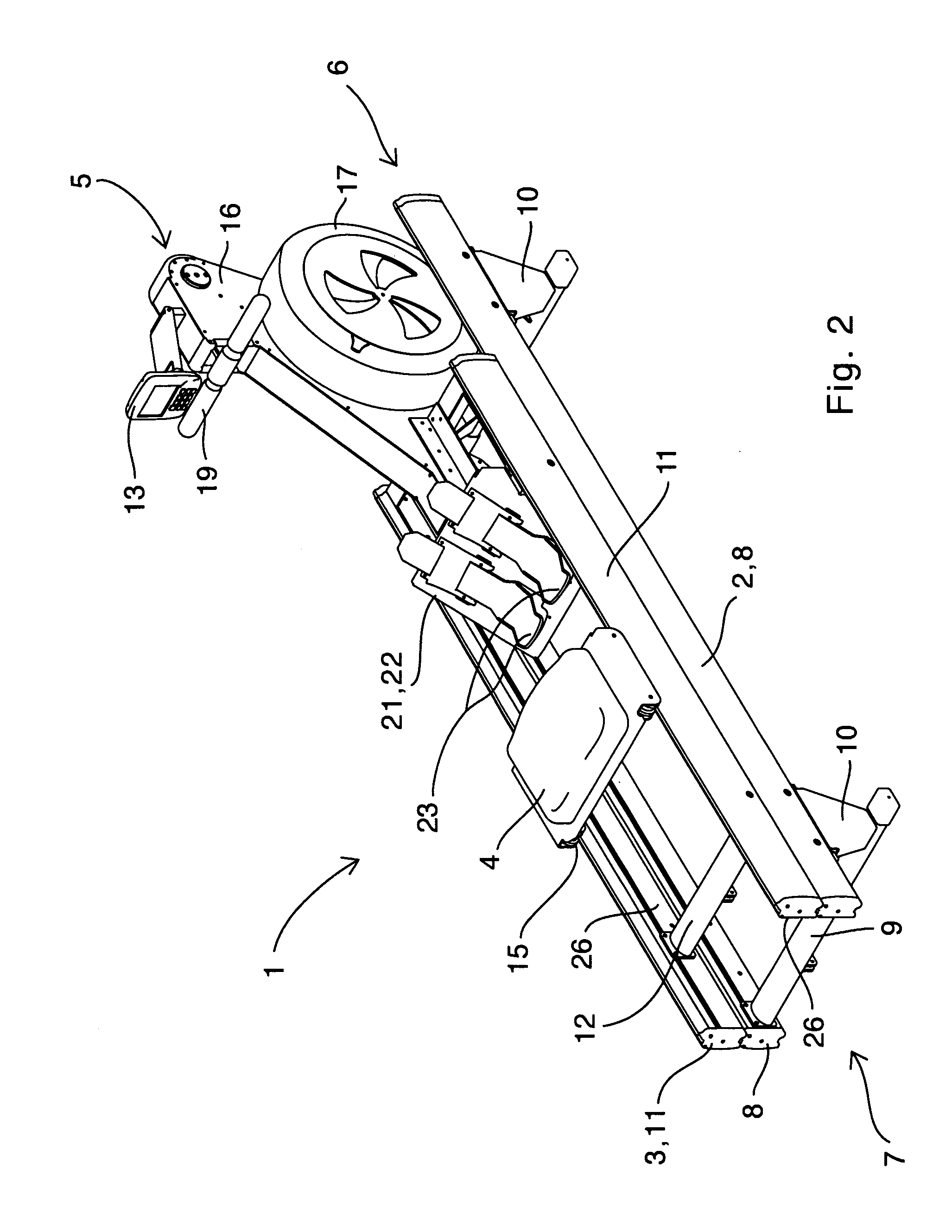
[0042]FIGS. 1 to 9 depict a rowing simulation machine 1 on which a user (rower) simulates a rowing motion. The rowing simulation machine 1 imparts a resistance to the rowing.

[0043]Rowing simulation machine 1 comprises a single base 2, a carriage 3, a seat 4, and an energy dissipating unit 5. Rowing simulation machine 1 has a fore-end 6, and aft-end 7.

[0044]Base 2 has a first pair of spaced apart rails 8 held in parallel relationship to each other by base cross-members 9. Base 2 also has ground engaging legs 10 which are height adjustable. Wheels 25 are attached to leg(s) 10 near the fore-end 6 of machine 1. Wheels 25 are provided so that they can be used to assist moving of machine 1, when machine is stood up so that its aft-end 7 is above its fore-end 6, for storage, space saving and cleaning of the floor beneath.

[0045]Carriage 3 has a second pair of spaced apart rails 11 held in parallel relationship to each other by carriage cross-members 12. Carriage 3 having rollers 14 disposed...


PUM


Abstract

Featured is a rowing simulation machine including a single base having a first pair of spaced apart rails; a carriage having a second pair of spaced apart rails and engaged with the first pair of rails and moveable therealong in a generally horizontal translation; a seat engaged with the second pair of rails and moveable therealong in a generally horizontal translation. Also included is an energy dissipating unit fixed to the carriage. The energy dissipating unit includes a frame for supporting a flywheel, the flywheel being rotatably mounted on a flywheel shaft; a handle; a drive device connected to the handle, for converting a translation of the handle into a flywheel rotation; and a take up device for rewinding and maintaining a predetermined tension on the drive device. The carriage includes a foot rest assembly disposed therein between the second pair of spaced apart rails.

Description

TECHNICAL FIELD[0001]The present invention relates to rowing simulation machines and in particular to dynamic rowing machines.BACKGROUND[0002]Rowing machines are well-known for the purposes of building up general fitness and / or for training specifically for rowing and related sports. Rowing machines allow the user to exercise both upper body and lower body strength by simulating roughly the movement required to propel a row boat through the water.[0003]There is a variety of prior art rowing machines, including stationary rowing machines used in gymnasiums, rowing clubs and the like. In many instances these stationary rowing machines are used as ergometers. One such prior art stationary rowing machine is shown in U.S. Pat. No. 4,396,188 (Dreissigacker et al). This machine has a monorail beam upon which a seat with rollers is able to slidably move therealong. A second beam (or arm) supporting a flywheel / fan mechanism is connected at the fore end of the monorail beam. The beam has foot...

Claims


Application Information

Patent Timeline
Patent Type & Authority Applications(United States)
IPC IPC(8): A63B69/06
CPCA63B21/0051A63B21/0088A63B21/225A63B2071/025A63B24/0062A63B2022/0079A63B22/0076
Inventor ROACH, MATTHEW D.
Owner ROACH MATTHEW D
Why Eureka
Try Eureka