Vortex Tube

a vortex and tube technology, applied in the field of fluid dynamics, can solve the problems of inefficiency of both cop ratios, and achieve the effect of improving efficiency and reducing the number of cop ratios

Inactive Publication Date: 2011-02-10
PAX SCI +1
View PDF77 Cites 23 Cited by
  • Summary
  • Abstract
  • Description
  • Claims
  • Application Information

AI Technical Summary

Problems solved by technology

Both COP ratios are generally viewed as inefficient, but an inherent limitation of fluid flow control that corresponds directly to a compressor component in the fluid flow control system.

Method used


Image

  • Vortex Tube
  • Vortex Tube
  • Vortex Tube

Examples


Embodiment Construction

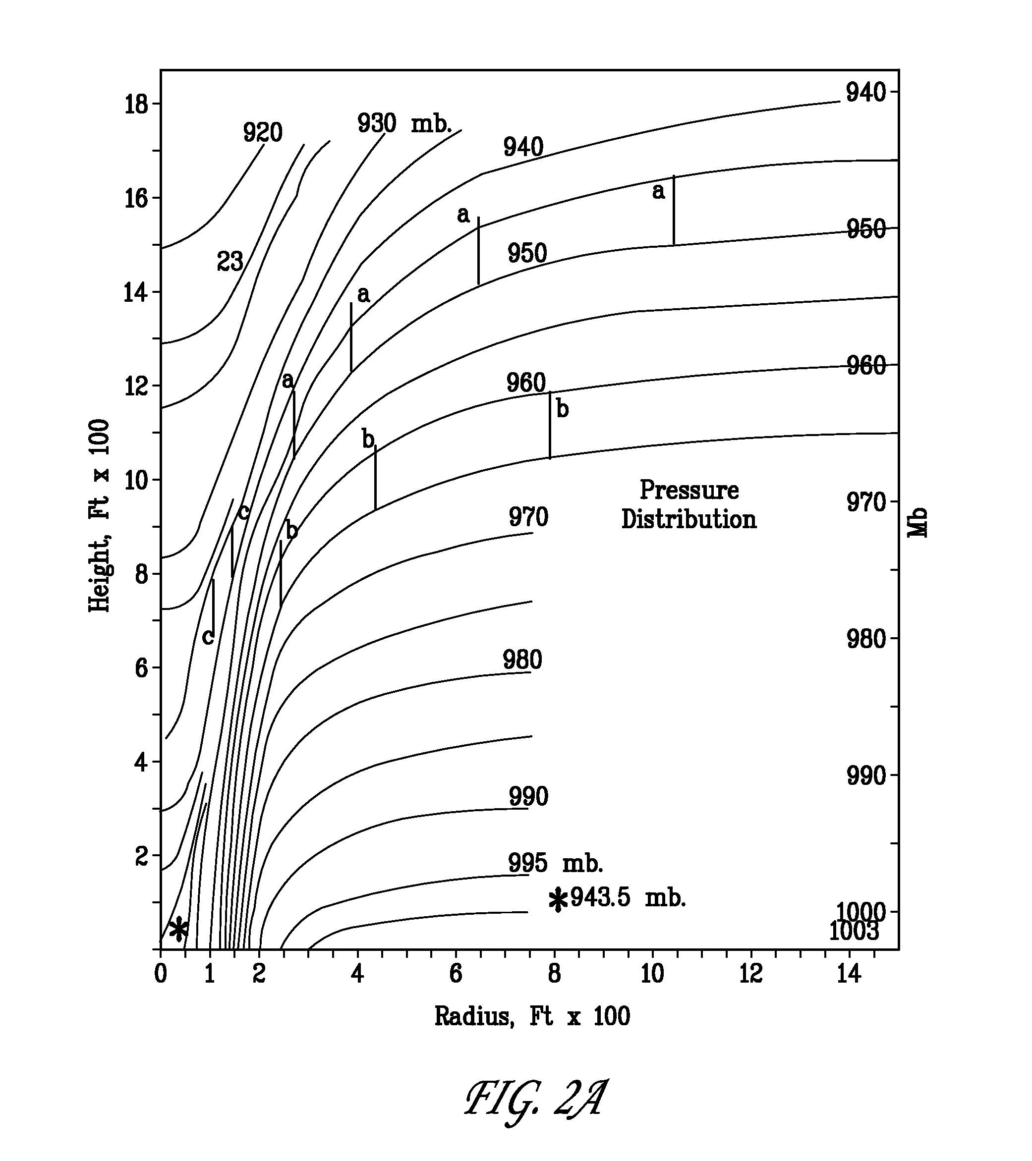
[0018]A tornado is a violent, rotating column of air. While tornadoes vary in shape and size, they typically form a visible condensation funnel. The tornado proper, however, refers to the vortex of wind—not the condensation funnel or ‘cloud.’ The central core of a tornado is calm with low pressure whereby fluid flow is slowly introduced from outside the vortex and into the rotating flow. Immediately outside a tornado, however, are very high velocities and intense fluid motion; velocity decreases with an increase in radius. The highest velocity trends close to the central core of the tornado and slowly decreases as the point of measurement moves to the outside in accordance with Bernoulli's Principle. The intensification of fluid motion in a tornado is a result of the ‘stretching’ of rotating fluid, which may occur through acceleration. The result is increased vortex motion. FIGS. 2A and 2B illustrate the pressure and velocity profile of a tornado, respectively.

[0019]The vortex of wi...


PUM


Abstract

A vortex tube allowing for control of the velocities, flow, and pressure differentials otherwise present in a free vortex like that found in a tornado is disclosed. The presently disclosed vortex tube may be used for the control and implementation of the otherwise chaotic aspects of a true tornado and vortex (i.e., with less energy and a narrowed and more focused and intense vortex) when implementing the critical flow regime in a fluid flow system.

Description

CROSS-REFERENCE TO RELATED APPLICATIONS[0001]The present application claims the priority benefit of U.S. provisional application No. 61 / 165,911 filed Apr. 2, 2009 and entitled “Vortex Tube,” the disclosure of which is incorporated by reference.BACKGROUND OF THE INVENTION[0002]1. Field of the Invention[0003]The present invention generally relates to fluid dynamics. The present invention more specifically relates to the creation and management of vortex flows, which may be implemented as a separator or ejector in a fluid flow control system.[0004]2. Description of the Related Art[0005]Industry generally requires the movement of fluid flow for any number of reasons and as might be related to any number of different applications. One example is in the context of air conditioning whereby heat energy is moved into or out of an enclosed space by means of a body of air. Another example includes water heating whereby heat energy is applied to a body of water in order to raise its temperature...

Claims


Application Information

Patent Timeline
Patent Type & Authority Applications(United States)
IPC IPC(8): F25B9/04
CPCF25B9/04B04C3/00
Inventor CHARAMKO, SERGUEIMANIAM, BALAJI
Owner PAX SCI
Why Eureka
Try Eureka