Weather seal system

a weather seal and system technology, applied in the direction of rain/draught deflectors, window/door frames, sills/thresholds, etc., can solve the problems of relatively increased exterior pressure and more problematic moisture intrusion

Active Publication Date: 2011-03-03
PELLA
View PDF32 Cites 9 Cited by
  • Summary
  • Abstract
  • Description
  • Claims
  • Application Information

AI Technical Summary

Benefits of technology

[0003]Some embodiments relate to a door assembly including a frame, a door, a first side seal, a lower seal and a first transition seal. The frame includes a top portion, a bottom portion, a first side portion, and a second side portion opposite the first side portion. The door is secured to the frame and has a top, a bottom, a first side, a second side opposite the first side, a front, and a back. The first side has a front portion toward the front of the door and a back portion toward the back of the door. The bottom has a front portion toward the front of the door and a back portion toward the back of the door. The first side seal is adapted to be secured substantially vertically between the first side portion of the door frame and the first side of the door and to contact the first side portion of the door frame and the first side of the door to form a first weather barrier toward the front portion of the first side of the door. The lower seal is adapted to be secured substantially horizontally between the bottom portion of the frame and the bottom of the door and to contact the bottom portion of the frame and the bottom of the door to form a lower weather barrier toward the back portion of the bottom of the door. The first transition seal is adapted to be secured between the first side portion of the door frame and the first side of the door and to contact the first side portion of the frame and the first side of the door to form a transition weather barrier extending between the first weather barrier and the lower weather barrier.

Problems solved by technology

As one might expect, moisture intrusion is more problematic in high moisture situations with relatively increased exterior pressure (e.g., as is the case near oceans or in storms due to wind and moist air).

Method used


Image

  • Weather seal system
  • Weather seal system
  • Weather seal system

Examples


Embodiment Construction

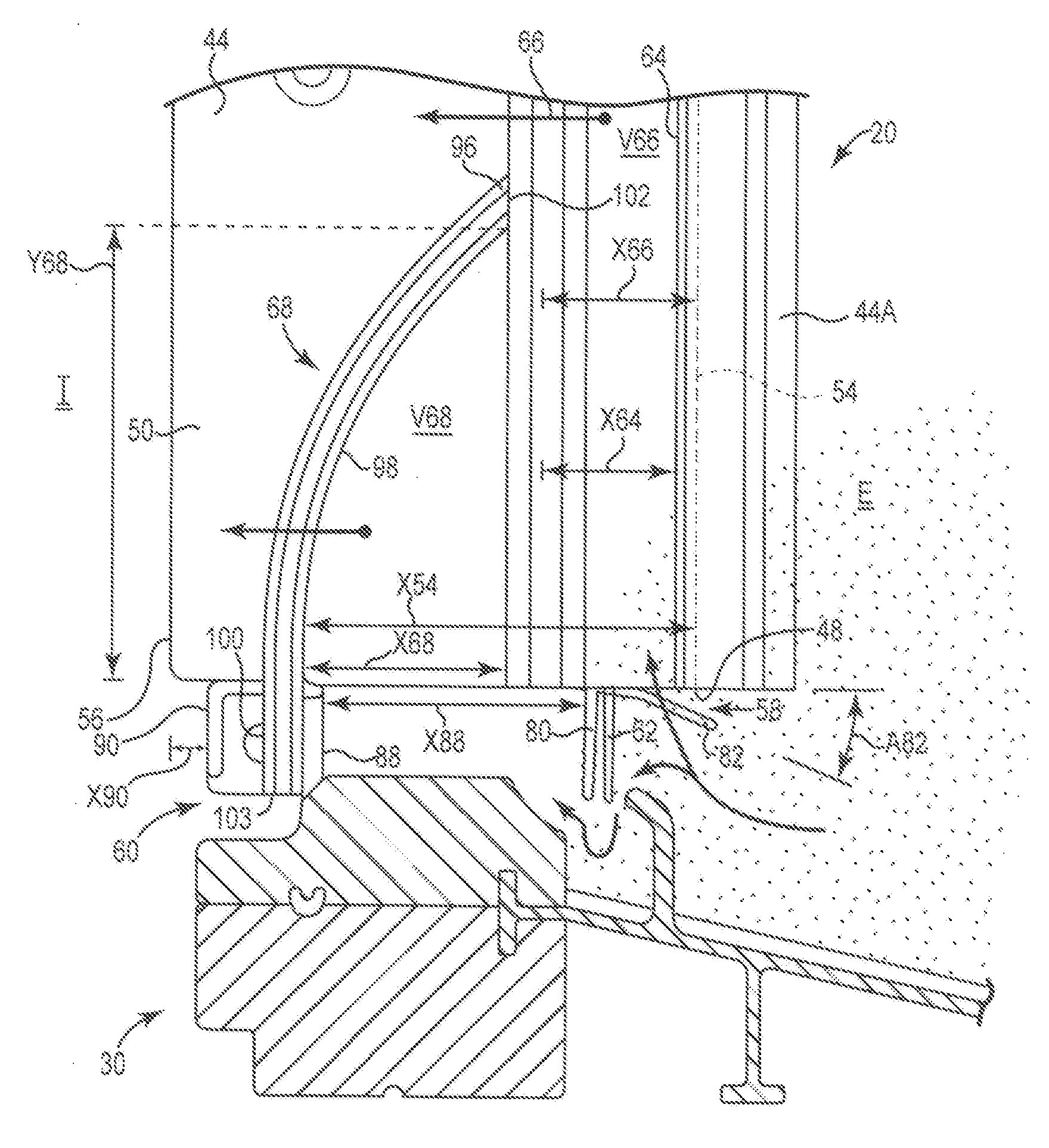
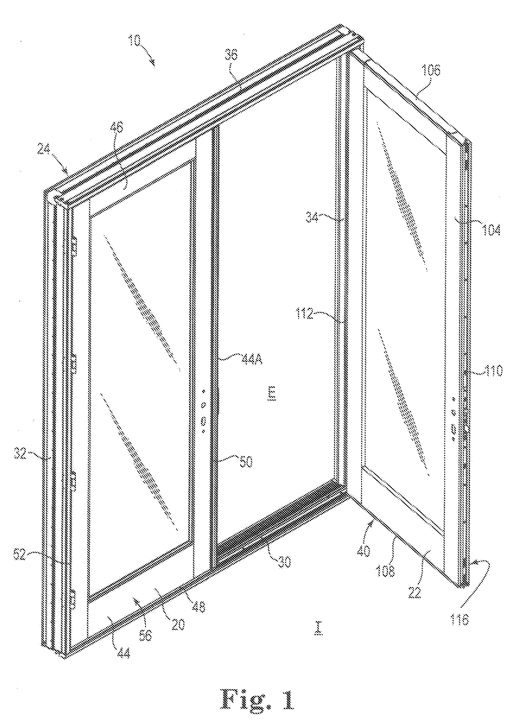
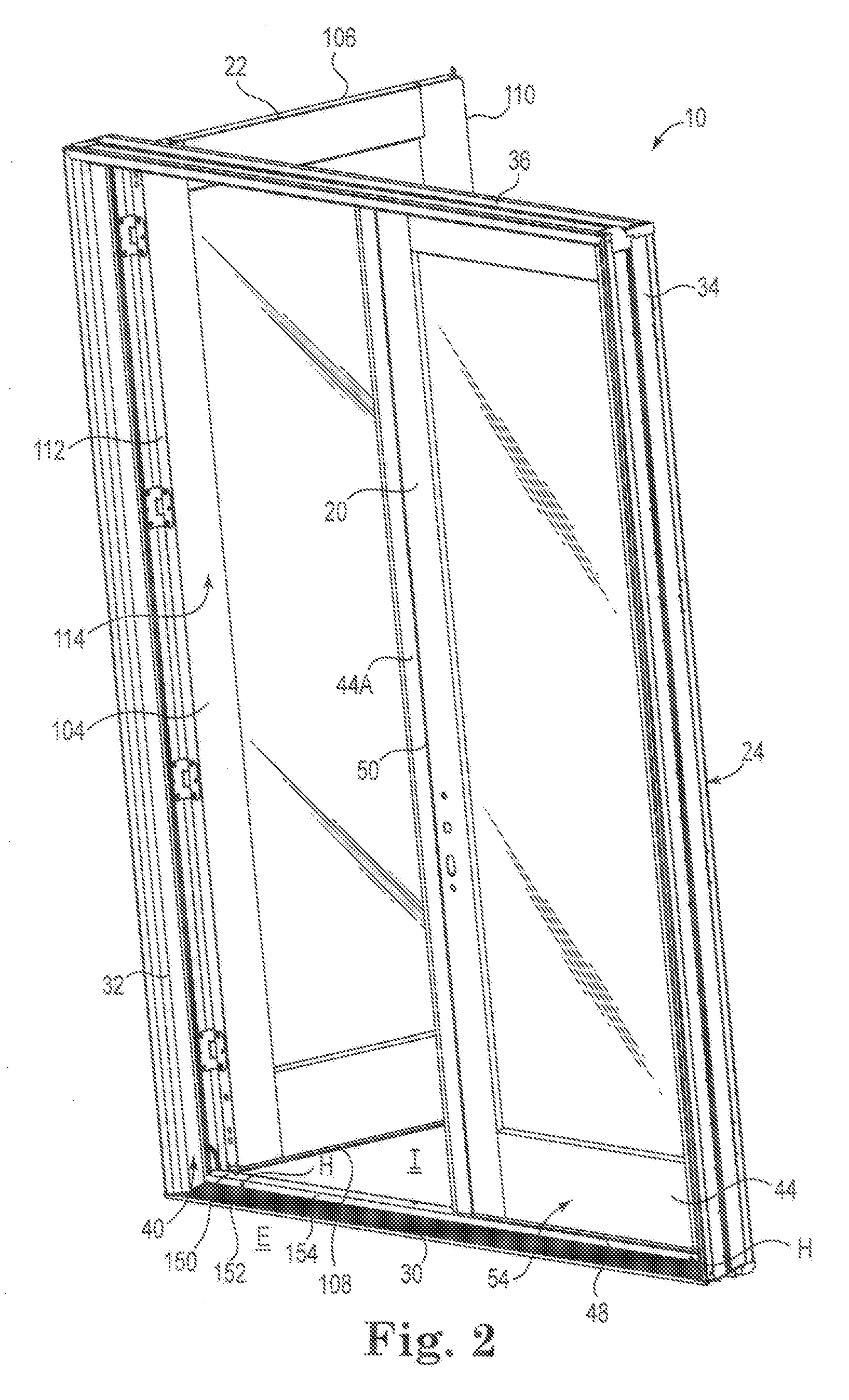
[0016]Various embodiments address a door assembly including a weather seal system forming a water barrier and an air barrier. The air barrier includes a sill portion, a frame portion, and a transition portion extending between the sill and frame portions. The transition portion extends inwardly and downwardly from the frame portion of the air barrier, toward an interior side of the door assembly, to the sill portion of the air barrier. At the corners of the door assembly, the transition portion provides a buffer zone, or transition zone of air at a greater spacing from the water barrier. In some embodiments, the transition zone supplies substantially dry air to any air leaks in air barrier at the lower corner(s) of the door assembly. Under some conditions, a sill area of the door assembly is particularly moist (e.g., atomized water droplets and / or other sources of moisture are often located at the exterior, lower area of the door assembly during a storm, near large bodies of water, ...


PUM

PropertyMeasurementUnit
non-zero angleaaaaaaaaaa
horizontal distanceaaaaaaaaaa

Abstract

Some aspects relate to weather seal systems for forming water barriers and air barriers. Some air barriers include a sill portion, a frame portion, and a transition portion extending between the sill and frame portions, where the transition portion extends inwardly and downwardly from the frame portion of the air barrier, toward an interior side of an associated door assembly, to the sill portion of the air barrier. The transition portion optionally provides a buffer zone, or transition zone of air at a greater spacing from the water barrier. In some embodiments, the transition zone is equilibrated to external pressures and supplies substantially dry air to air leaks in the air barrier.

Description

BACKGROUND[0001]In order to reduce the likelihood of moisture ingress into a dwelling or other structure, exterior door assemblies include sealing systems (e.g., gaskets, flanges, and the like) between the door and door frame. As one might expect, moisture intrusion is more problematic in high moisture situations with relatively increased exterior pressure (e.g., as is the case near oceans or in storms due to wind and moist air). In the past, in order to combat moisture ingress, various solutions requiring raised and / or moisture-wicking sills have been implemented.SUMMARY[0002]Some embodiments relate to a weather seal system forming a water barrier and an air barrier. In some embodiments, the air barrier includes a sill portion, a frame portion, and a transition portion extending between the sill and frame portions. The transition portion extends inwardly and downwardly from the frame portion of the air barrier, toward an interior side of an associated door assembly, to the sill por...

Claims


Application Information

Patent Timeline
Patent Type & Authority Applications(United States)
IPC IPC(8): E06B7/16E06B1/34E06B3/00
CPCE06B7/2305E06B7/16E06B7/26
Inventor SCHRODER, PAUL D.
Owner PELLA
Why Eureka
Try Eureka