Myopia control means

Active Publication Date: 2011-03-03
BRIEN HOLDEN VISION INST (AU) +1
View PDF78 Cites 50 Cited by
  • Summary
  • Abstract
  • Description
  • Claims
  • Application Information

AI Technical Summary

Benefits of technology

[0039]From another aspect the invention provides a method for reducing the progression of myopia of an eye, the method comprising placing an ophthalmic device, for example a contact lens, on an eye wherein the device comprises a predetermined central sphere power which is defined by an amount of myopia of an eye, the device further including a pred

Problems solved by technology

That is, the focusing power of the eye is too strong ‘at distance’ for the accommodative power of the eye.
Progressive myopia, which is generally considered to be caused by gradually increasing eye length rather than lens power, can be a serious condition that leads to increasing visual impairment despite the use of successively stronger corrective lenses.
It is therefore assumed that, in progressive myopia, this feedback mechanism goes awry and causes the eye to continue to lengthen excessively even though good corrective lenses are used.
It has been proposed, for example, that the feedback mechanism controlling eye growth is somehow upset by deficiencies in the accommodative effort of the eye due to excessive near work.
The deficiency is considered to manifest as lag of accommodation (imprecise and insufficient accommodation) at near resulting in defocus, which stimulates further undesirable axial elongation of the eye.
However, data from clinical studies showed poor efficacy over the use standard refractive correction using negative power lenses.
These lenses, in which both distance and near zones lie within the normal pupil diameter or ‘optic zone’ of the lens, have the disadvantage that they present two central images to the retina at all times so that image quality is always degraded.
In addition, the success of such treatment methods appears to be limited and variable.
However, we note that the add

Method used


Image

  • Myopia control means
  • Myopia control means
  • Myopia control means

Examples


Example

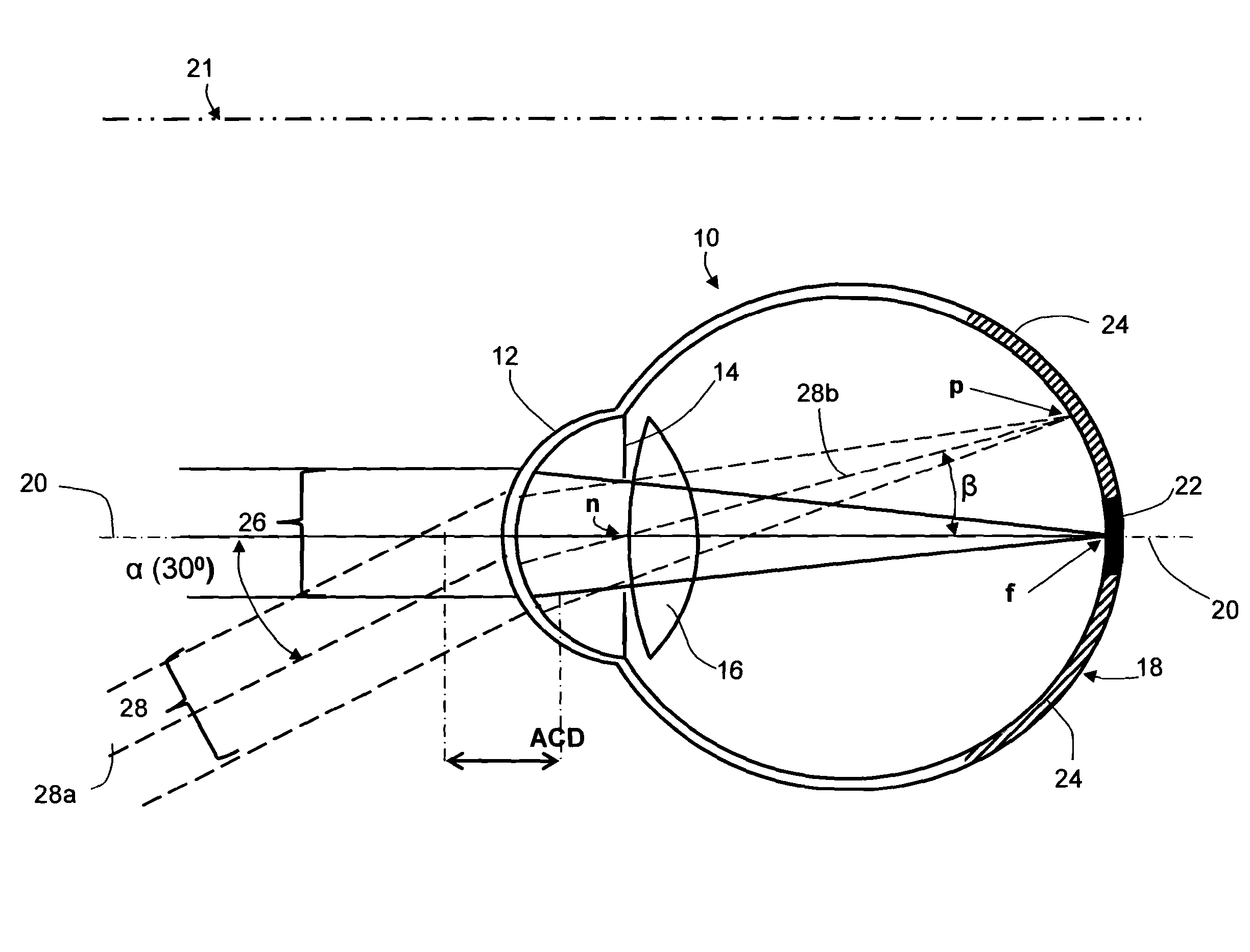
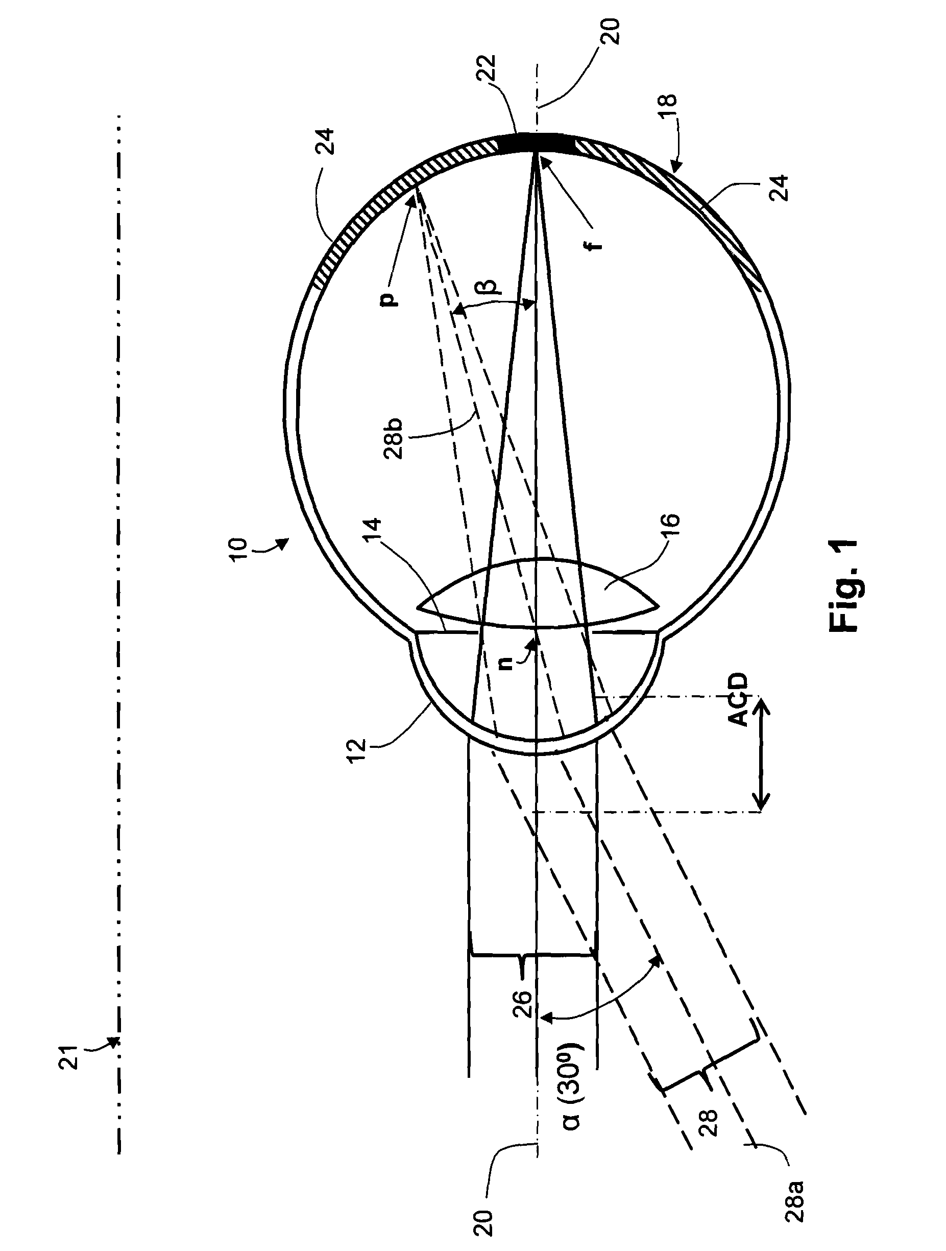
[0070]FIG. 1 is a greatly simplified diagrammatic sectional plan of a normal left human eye 10 having a cornea 12, iris 14, lens 16, retina 18 and visual axis 20, the nasal plane between the eyes (or mid-visual axis) being indicated at 21. Retina 18 is divided into (i) a central portion 22 (solid black) that is used for central vision and includes the fovea, the most sensitive portion of the retina, and (ii) an annular peripheral portion 24 (hatched) which is much larger in area than central portion 22 but is less sensitive. In a normal or emmetropic eye with a straight-ahead gaze (on axis 20) directed at distance, an axial central beam 26 from a distant object will be brought to focus at f on the fovea in the middle of central region 22 of retina 18 providing good visual acuity. At the same time, a peripheral or off-axis beam 28 from a distant object will be brought to focus at point p on peripheral retina 24, it being assumed that the central ray 28a of peripheral beam 28 intersec...


PUM


Abstract

Sets, kits or stocks of anti-myopia contact or spectacle lenses, along with methods for their use, that do not require a clinician to measure peripheral refractive error in the eyes of myopic patients. Extensive surveys have shown that lenses having peripheral powers or defocus set in accordance with central corrective power will cover almost all normal myopes not worse than −6D central refractive error. In one example, a kit or set of lenses (50, FIG. 15) can have multiple parts or sub-sets (52, 54) each comprising a compartmented container (56a, 56b) with lenses (58a, 58b) arranged according to increments of central corrective power (59a, 59b). The lenses (58a) of the first part (52) have four steps (60a, 61a, 62a, 64a) of peripheral power or defocus to pro vide therapeutic effect and, while the lenses (58b) of the second part (54) also have four steps (60b, 61b, 62b, 64b), the level of therapeutic effect is higher. Other examples of sets, kits and stocks, as well as examples of lenses themselves, are disclosed together with methods of use.

Description

BACKGROUND OF THE INVENTION[0001]1. Field of the Invention[0002]The current invention relates to means for inhibiting or ameliorating the progression of myopia, particularly in young people, and includes both methods and apparatus. The methods include procedures for the prescription, selection, fitting and supply of contact and spectacle lenses. The apparatus includes stocks, sets or kits of such lenses and to lenses or lens components per se.[0003]In this specification contact and spectacle lenses capable of—or intended for—both correcting central refractive error and inhibiting the progression (increasing severity) of myopia over time are termed ‘anti-myopia’ lenses.[0004]2. Background and Discussion of Prior Art[0005]Myopia (short-sightedness) is a disorder of the eye in which accommodation of the natural lens can bring near objects but not distant objects to focus on the central retina, distant objects being focused in front of (anterior to) the retina. That is, the focusing pow...

Claims


Application Information

Patent Timeline
IPC IPC(8): G02C7/04
CPCG02C7/02G02C7/04G02C7/06G02C2202/24G02C7/041G02C2202/08G02C7/022A61B3/0025G02C7/027G02C7/044G02C13/003G02C2202/16
Inventor MARTINEZ, ALDO ABRAHAMHO, ARTHURSANKARIDURG, PADMAJA RAJAGOPALLAZON, PERCY FABIANHOLDEN, BRIEN ANTHONYPAYOR, RICKSCHMID, GREGOR F.
Owner BRIEN HOLDEN VISION INST (AU)
Why Eureka
Try Eureka