

Portable electronic device
- Summary
- Abstract
- Description
- Claims
- Application Information
AI Technical Summary
Benefits of technology
Problems solved by technology
Method used
Image


Examples
Embodiment Construction
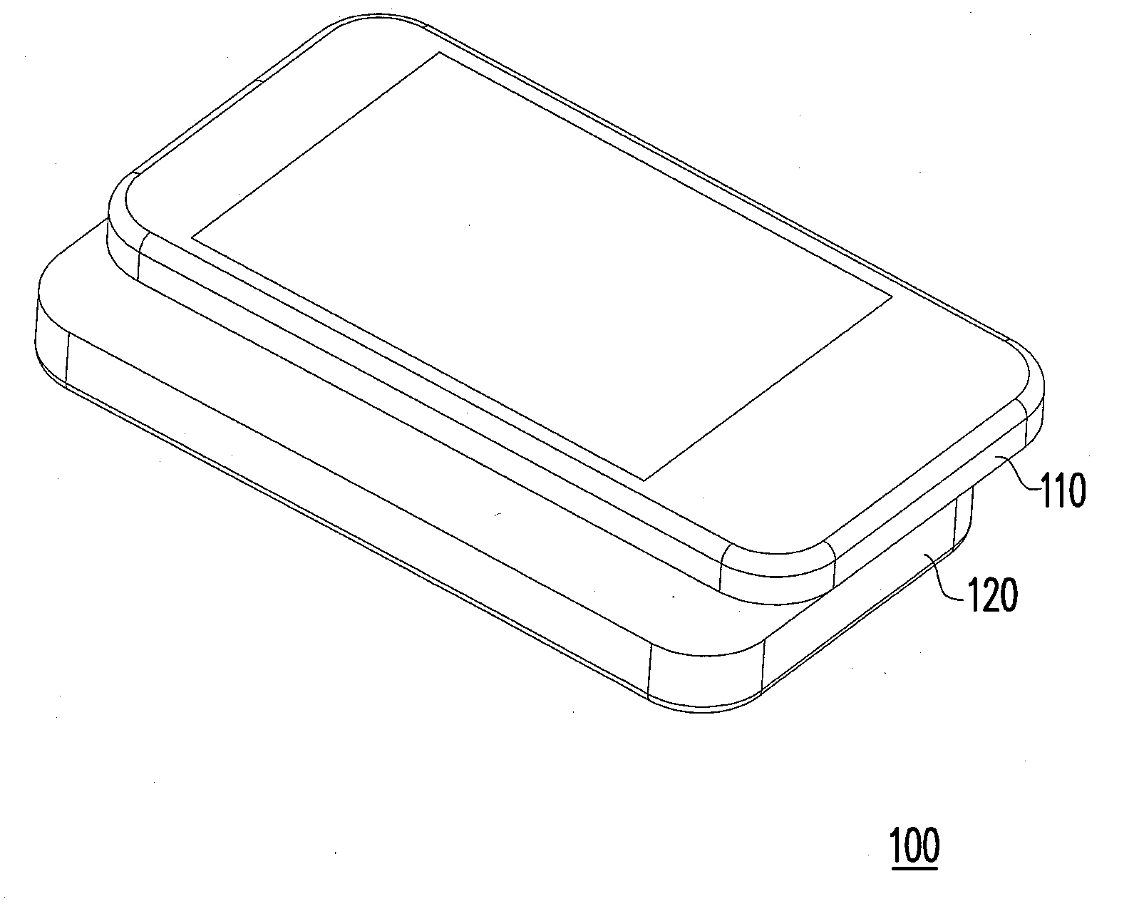
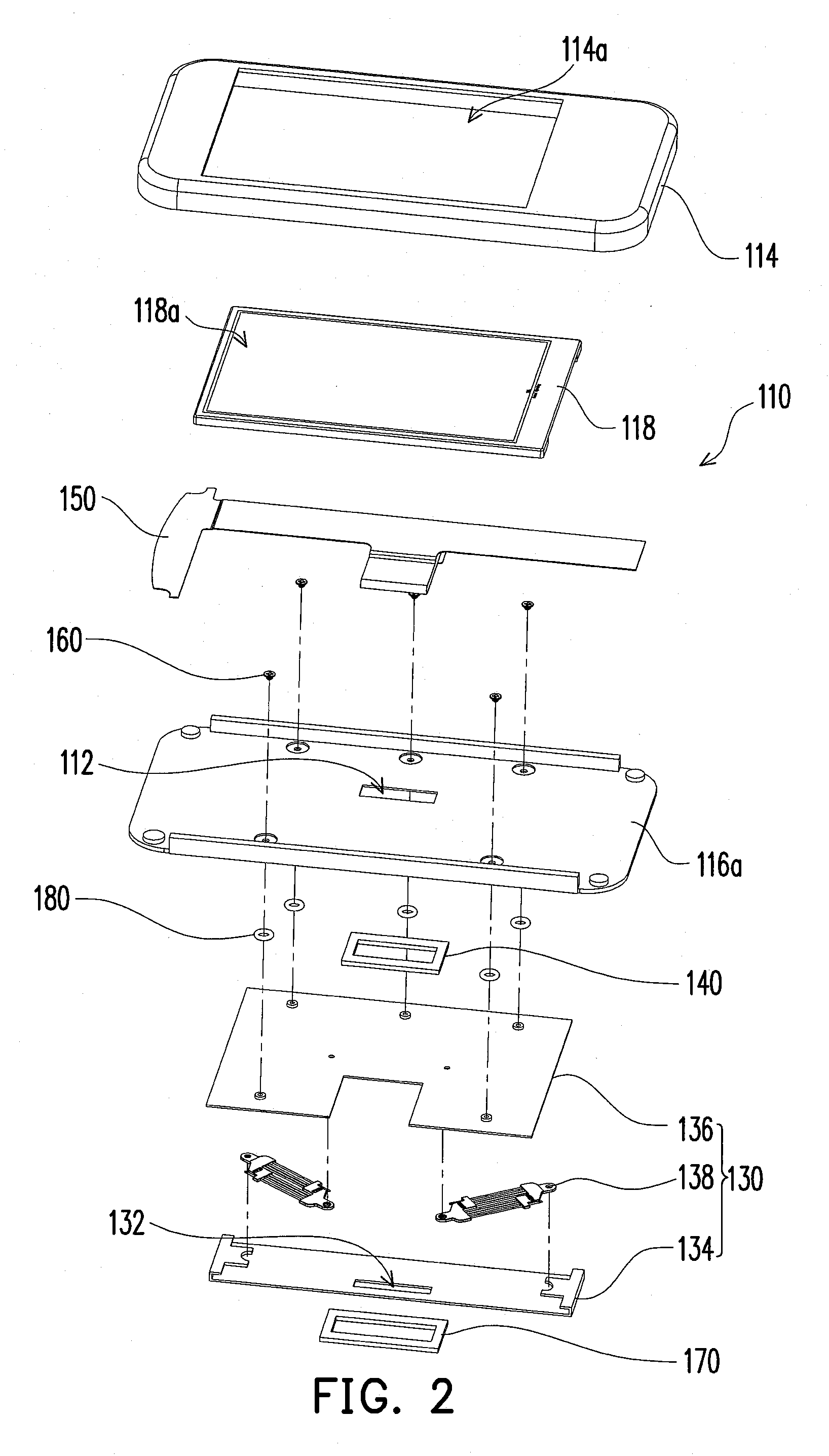
FIG. 1 is a schematic view illustrating a portable electronic device according to an embodiment of the application. FIG. 2 is an exploded view of a first body and a sliding module of the portable electronic device in FIG. 1. Referring to FIG. 1 and FIG. 2, in the present embodiment, a portable electronic device 100 includes a first body 110, a second body 120, a sliding module 130, and a first seal member 140. The sliding module 130 is disposed between the first body 110 and the second body 120, so that the first body 110 slides relative to the second body 120.
FIG. 3 is a sectional view of the first body of the portable electronic device in FIG. 1. FIG. 4 is a cross-sectional view of the portable electronic device in FIG. 3. Referring to FIG. 3 and FIG. 4, the portable electronic device 100 further includes a flexible electrical member 150, such that the first body 110 is electrically connected to the second body 120 via the flexible electrical member 150 (indicated in FIG. 1). In o...
PUM
 Abstract
Description
Claims
Application Information