
Assembly for securing the outer end of the balance-spring of a sprung balance device for a timepiece

a technology of sprung balance and outer end, which is applied in the direction of frequency setting mechanism, instruments, etc., can solve the problems of balance-spring or stud holder locking screw coming off, loss, etc., and achieves the effect of reducing the difficulty of handling and facilitating the positioning of the balance-spring

Active Publication Date: 2011-03-03
GLASHUETTER UHRENBETRIEB GMBH
View PDF9 Cites 12 Cited by
  • Summary
  • Abstract
  • Description
  • Claims
  • Application Information

AI Technical Summary

Benefits of technology

[0004]The invention proposes various means for avoiding this type of drawback, particularly in order to make it easier to position the balance-spring and adjust its active length and thus to minimise the difficult handling that has to be performed.
[0008]This device makes it easier to position and adjust the active length of the balance-spring. This ease of handling also allows the active length to be more finely adjusted.
[0017]According to another advantageous embodiment, the channel for securing the balance-spring is convex, with a centre of curvature that approximately matches the balance-spring axis. Owing to this feature, the radii of curvature of the portion of balance-spring to be secured and of the channel are approximately matching, for easier and more precise assembly.
[0018]In a variant, the stud is has an anti-friction pad arranged on the surface of the stud that cooperates with the balance-spring. The presence of this element makes the longitudinal sliding and adjustment of the balance-spring easier.
[0027]completely tightening the locking screw so as to prevent any lateral sliding of the outer end of the balance-spring in the channel.

Problems solved by technology

In practice, during assembly and / or adjustment, it is difficult to handle these various elements, since access is restricted and the parts are of very small dimensions.
Moreover, with this type of configuration, it is common for the balance-spring or stud holder locking screw to come off and / or be lost when it is handled, such as during adjustment of the active length of the balance-spring.

Method used


Image

  • Assembly for securing the outer end of the balance-spring of a sprung balance device for a timepiece
  • Assembly for securing the outer end of the balance-spring of a sprung balance device for a timepiece

Examples


Embodiment Construction

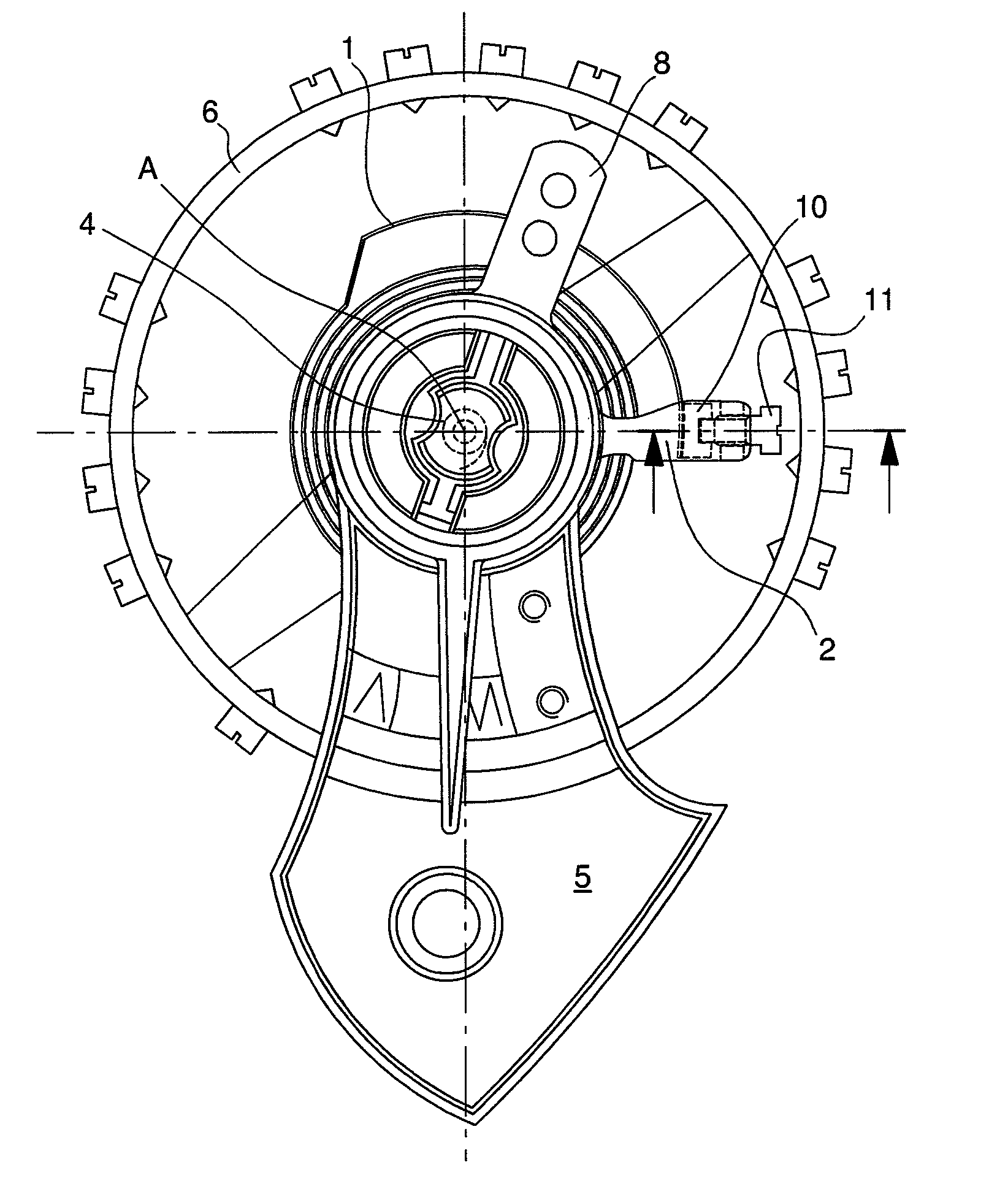
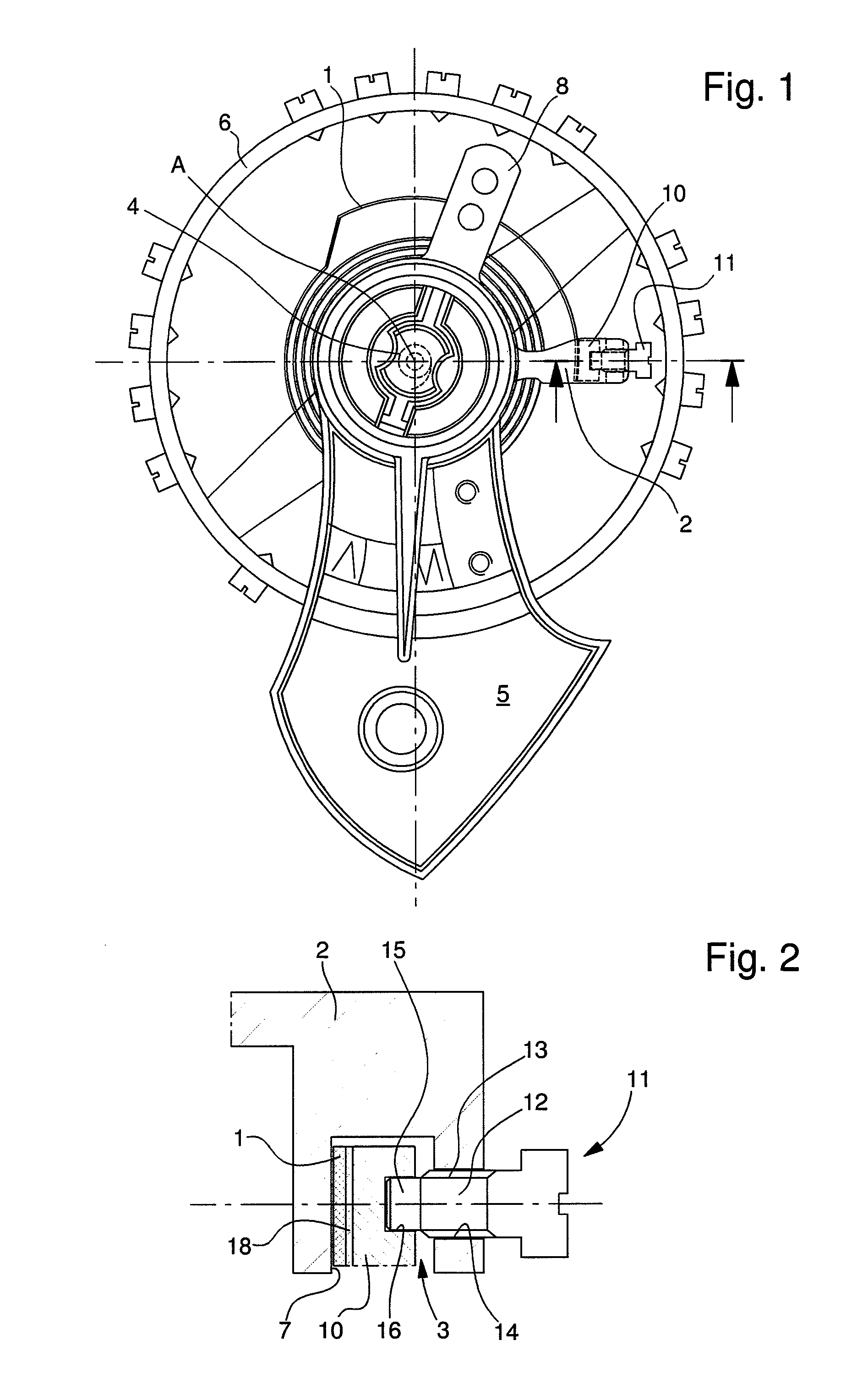
[0031]FIG. 1 illustrates a view of a sprung balance device for a timepiece, showing balance-cock 5, used in a conventional manner for pivoting one of the ends of staff A of balance 6. The other end of balance staff A pivots on the bottom plate in a conventional manner. Also in a conventional manner, a collet 4 is driven onto the balance staff and allows the central portion of balance-spring 1 to be secured.

[0032]Balance-cock 5 is also used as a support for a balance-spring stud holder 2 for securing the outer end of balance-spring 1. Balance-cock 5 also carries an index 8, for cooperating with the outer coil of balance-spring 1, upstream of the end that will be secured.

[0033]In the example illustrated in FIGS. 1 and 2, balance-spring stud holder 2 is extended radially relative to balance staff 6, towards the outer coils of the balance-spring. The angular positioning of stud holder 2 is such that it allows the free outer end of balance-spring 1 to be secured. There is a convex channe...


PUM


Abstract

Assembly for securing the outer end of the balance-spring (1) of a sprung balance device for a timepiece that includes a balance-spring stud holder (2) for housing a balance-spring stud (10), against which the balance-spring (1) can be locked, a screw (11) for locking the stud, for securing the balance-spring (1) by insertion between the stud (10) and a back face (7), the locking screw (11) including a tip (15) in the extension of the threaded body (12) at the opposite end to the screw head, and the stud (10) including a housing (16) in which the tip (15) can be inserted. The corresponding watch and method of securing the outer end of the balance-spring are also provided.

Description

[0001]This application claims priority from European Patent Application No. 09168602.2 filed Aug. 25, 2009, the entire disclosure of which is incorporated herein by reference.FIELD OF THE INVENTION[0002]The invention concerns an assembly for securing the outer end of the balance-spring of a sprung balance device for a timepiece. It also concerns a corresponding sprung balance device for a timepiece, and the associated timepiece.STATE OF THE PRIOR ART[0003]In a mechanical watch, it is usual practice to use a regulating member comprising a sprung balance device. Conventionally, the inner end of the balance-spring is fixed to a collet on the pivoting balance staff. In order to fix and position the outer end of the balance-spring, it is known to use a balance-spring stud holder housing a balance-spring stud, in association with a locking screw for locking the balance-spring stud against the portion of the balance-spring engaged in the stud holder. In an assembly of this type, the stud h...

Claims


Application Information

Patent Timeline
IPC IPC(8): G04B17/20
CPCG04B18/023G04B17/325
Inventor SCHMIEDCHEN, CHRISTIAN
Owner GLASHUETTER UHRENBETRIEB GMBH
Learn More