Display assembly with cable stop

a technology of display stands and cable stops, which is applied in the direction of burglar alarm mechanical actuation, lock applications, instruments, etc., can solve the problems of not being able to read the information, unable to handle the article, and having a difficult time protecting the box containing various merchandise and other similarly structured packages

Inactive Publication Date: 2011-03-24
CHECKPOINT SYST INC
View PDF12 Cites 84 Cited by
  • Summary
  • Abstract
  • Description
  • Claims
  • Application Information

AI Technical Summary

Problems solved by technology

Retail stores have a difficult time protecting boxes containing various merchandise and other similarly structured packages, or protecting such containers from being opened and the contents thereof being removed without authorization from store personnel or from being damaged while on display.
The store is faced with the problem of how to protect these expensive articles from theft while displaying them for sale.
The consumer can view the article through the glass but is not able to handle the article or read any of the information about the article that may be printed on the box, unless a store clerk removes the article from the case.
However, in large retail stores, the problem then arises of getting the selected merchandise to the customer after the customer wishes to purchase the same without subjecting the merchandise to theft.
However, this makes the boxes susceptible to theft and requires additional sales personnel.
The consumer has no chance to inspect the merchandise before purchasing, and if they are not satisfied they must undergo the inconvenience of returning the merchandise for a refund.
This requires additional work by the retail personnel, and if the cables are not properly rewound these cables will become tangled with other cables creating a storage problem and requiring additional work for reuse and replacement on a different package.

Method used


Image

  • Display assembly with cable stop
  • Display assembly with cable stop
  • Display assembly with cable stop

Examples


Embodiment Construction

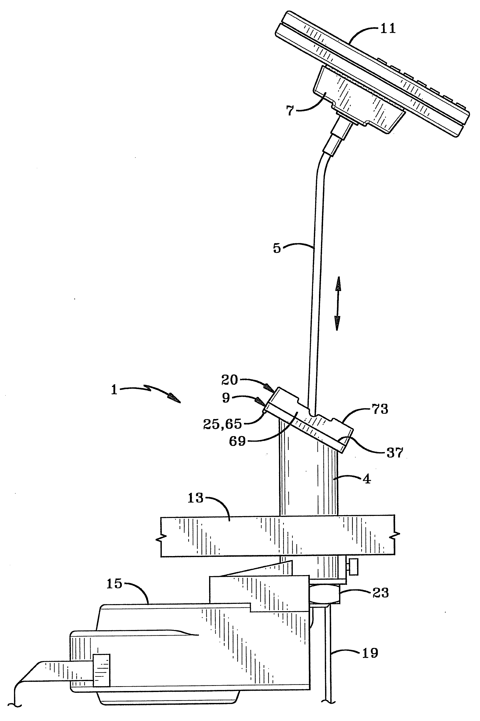
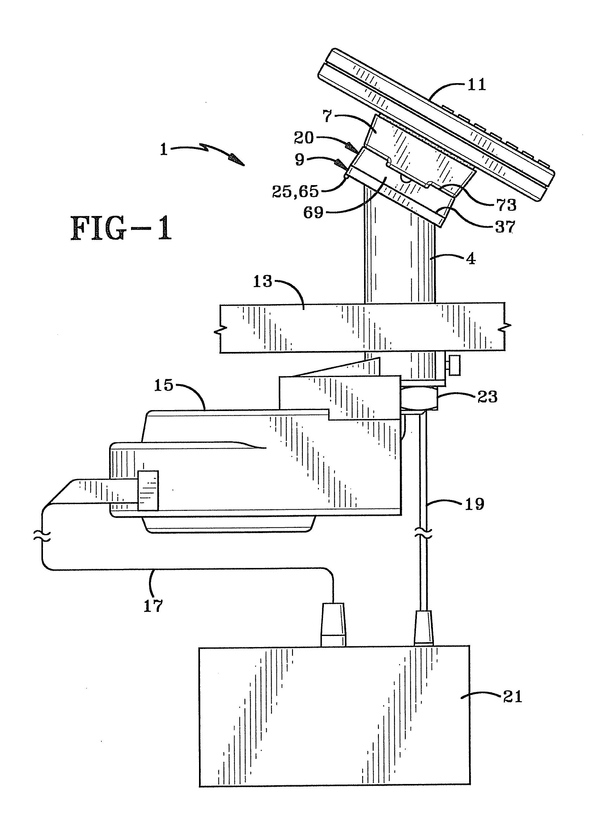
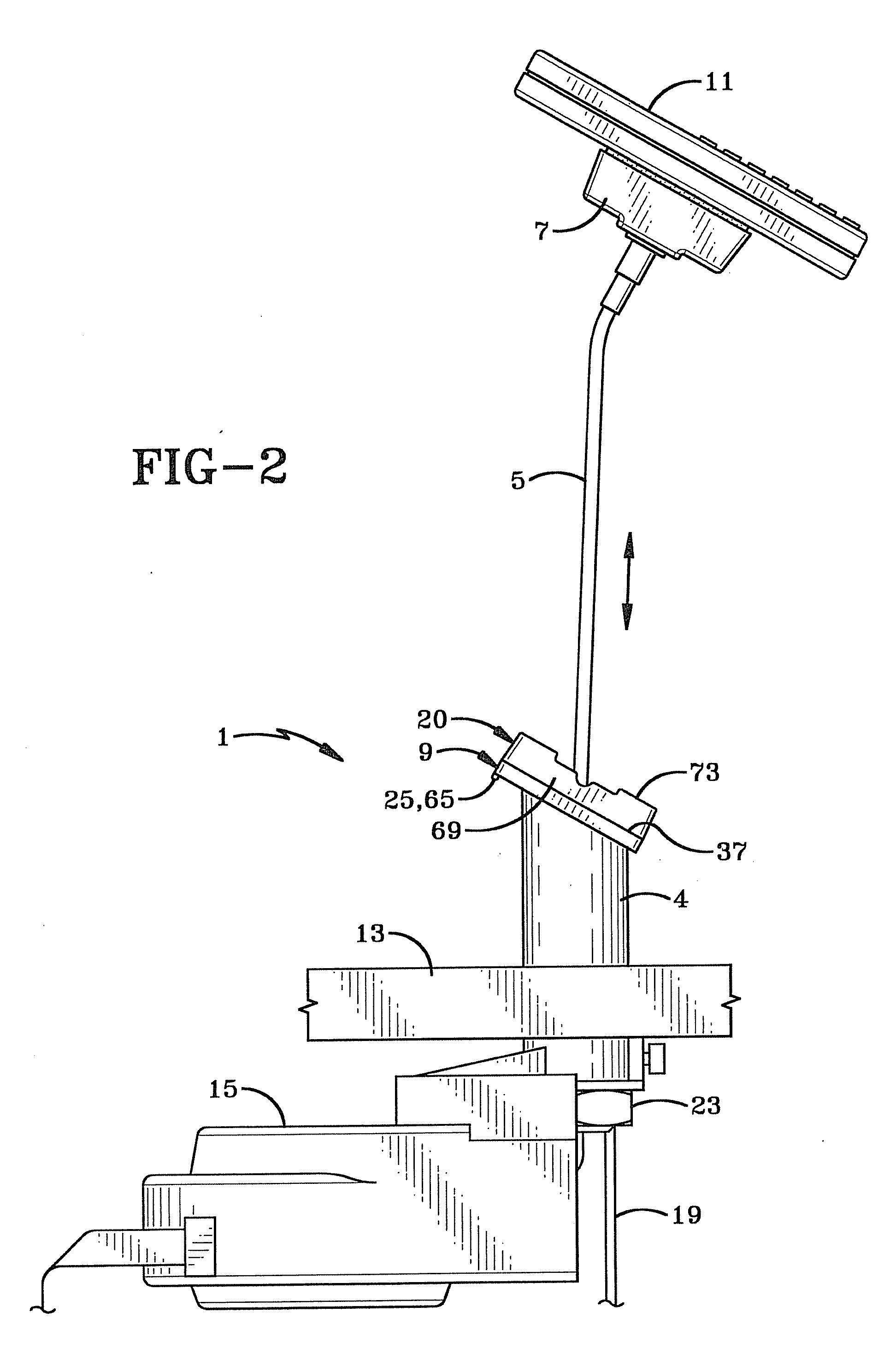
[0027]Described herein are example methods and other embodiments associated with securely displaying consumer merchandise. Referring to FIG. 1, in the preferred embodiment, a display assembly 1 includes a base cover 4, a tether 5, a mounting member 7, a base plate 9, and a mounting adapter 20. A display item 11 may be securely attached to the mounting member 7. The display item 11 may be a consumer electronic device such as a digital camera or other electronic device. As shown in FIG. 2, a tether 5 is connected between the mounting member 7 allowing the mounting member 7 and display item 11 combination to be removed from the mounting adapter 20. The other end of the tether 5 may be securely attached to a recoiler 15. The recoiler 15 is in turn securely attached to a physical object such as a display case so that the tether 5 is not easily removed. The tether 5 allows a consumer to remove the display item 11 and mounting member 7 combination in order to view and touch the display ite...


PUM


Abstract

Methods and other embodiments associated with a display stand with a tether stop are presented. In the preferred embodiment, a display stand includes a base, a mounting member, a tether, a recoiler, and a cable stop. The mounting member is adapted for mounting thereon a display item and is movable between a mounted position in contact with the base. The mounting member is configured to be removed from the base to facilitate viewing and handling of the display item. The tether includes a connector located at one end of the tether to attach the tether to the mounting member. The recoiler recoils the tether. The cable stop moves to a first position to allow the connector to pass through an opening in the base and to a second position to prevent the connector from passing through the opening.

Description

CROSS REFERENCE TO RELATED APPLICATIONS[0001]This application claims priority from U.S. Provisional Application Ser. No. 61 / 245,038 filed Sep. 23, 2009; the disclosure of which is incorporated herein by reference.BACKGROUND OF THE INVENTION[0002]1. Technical Field[0003]This invention relates generally to display stands for merchandise. More particularly, the invention relates to a display stand which allows the handling of an item of merchandise. Specifically, the invention relates to a display stand that tethers an item of merchandise to the display stand with a tether that will sound an alarm if the tether is cut.[0004]2. Background Information[0005]Retail stores have a difficult time protecting boxes containing various merchandise and other similarly structured packages, or protecting such containers from being opened and the contents thereof being removed without authorization from store personnel or from being damaged while on display. Consumers often want to visually inspect t...

Claims


Application Information

Patent Timeline
Patent Type & Authority Applications(United States)
IPC IPC(8): G08B13/12A47F1/04E05B73/00B65H75/48
CPCA47F7/024G08B13/1463B65H75/42Y10T70/5009
Inventor RAPP, MICHAELBELDEN, JR., DENNIS D.
Owner CHECKPOINT SYST INC
Why Eureka
Try Eureka