Multi-functional cooking stove

Inactive Publication Date: 2011-03-31
AFIRE
View PDF12 Cites 19 Cited by
  • Summary
  • Abstract
  • Description
  • Claims
  • Application Information

AI Technical Summary

Benefits of technology

[0009]Another main object of the present invention is to provide a cooking stove that centers the heat energy efficiently.
[0010]Yet another main object of the present invention is to provide a cooking stove that is easy to catch fire.
[0012]Thereby, the cooking stove can center the heat energy and be adapted for cooking manners such as frying, boiling, stewing, sauteing, hot-potting, broiling and roasting. In addition, the stove element can be taken out of the stove body for the user to easily catch fire. Thereafter, the user can transport the stove element with the help of the position frame and then place the stove element and the position frame in the stove body.

Problems solved by technology

The Fuel such as charcoal is displaced between the web partition and the stove shell, preventing the grease and barbecue sauce from directly dripping on the charcoal and causing hazard or smoke.

Method used


Image

  • Multi-functional cooking stove
  • Multi-functional cooking stove
  • Multi-functional cooking stove

Examples


first embodiment

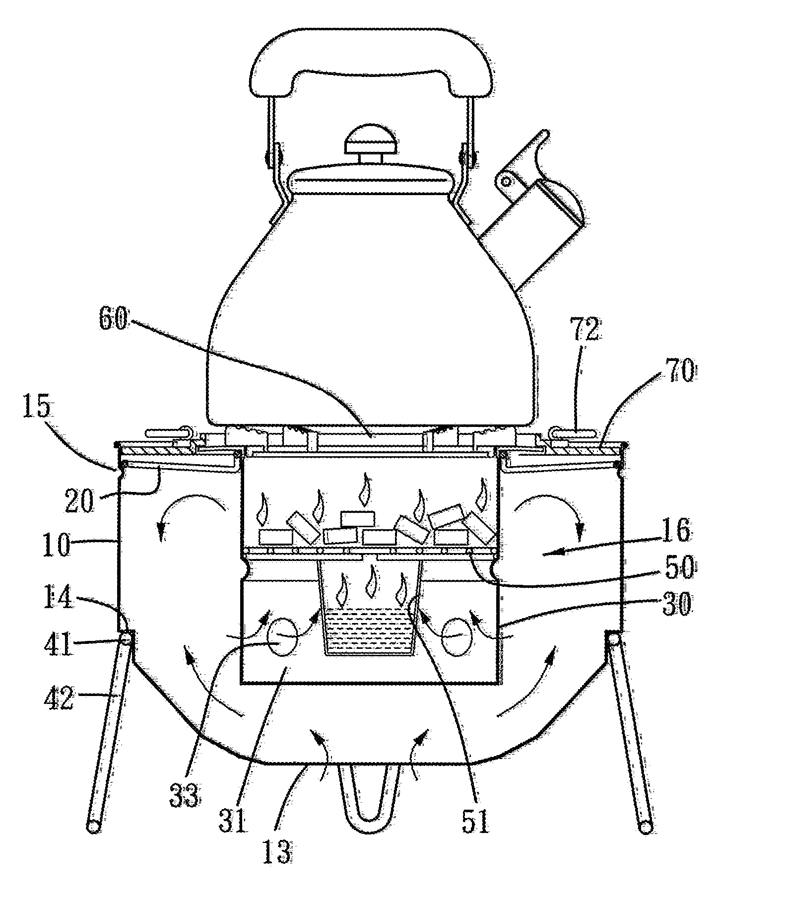
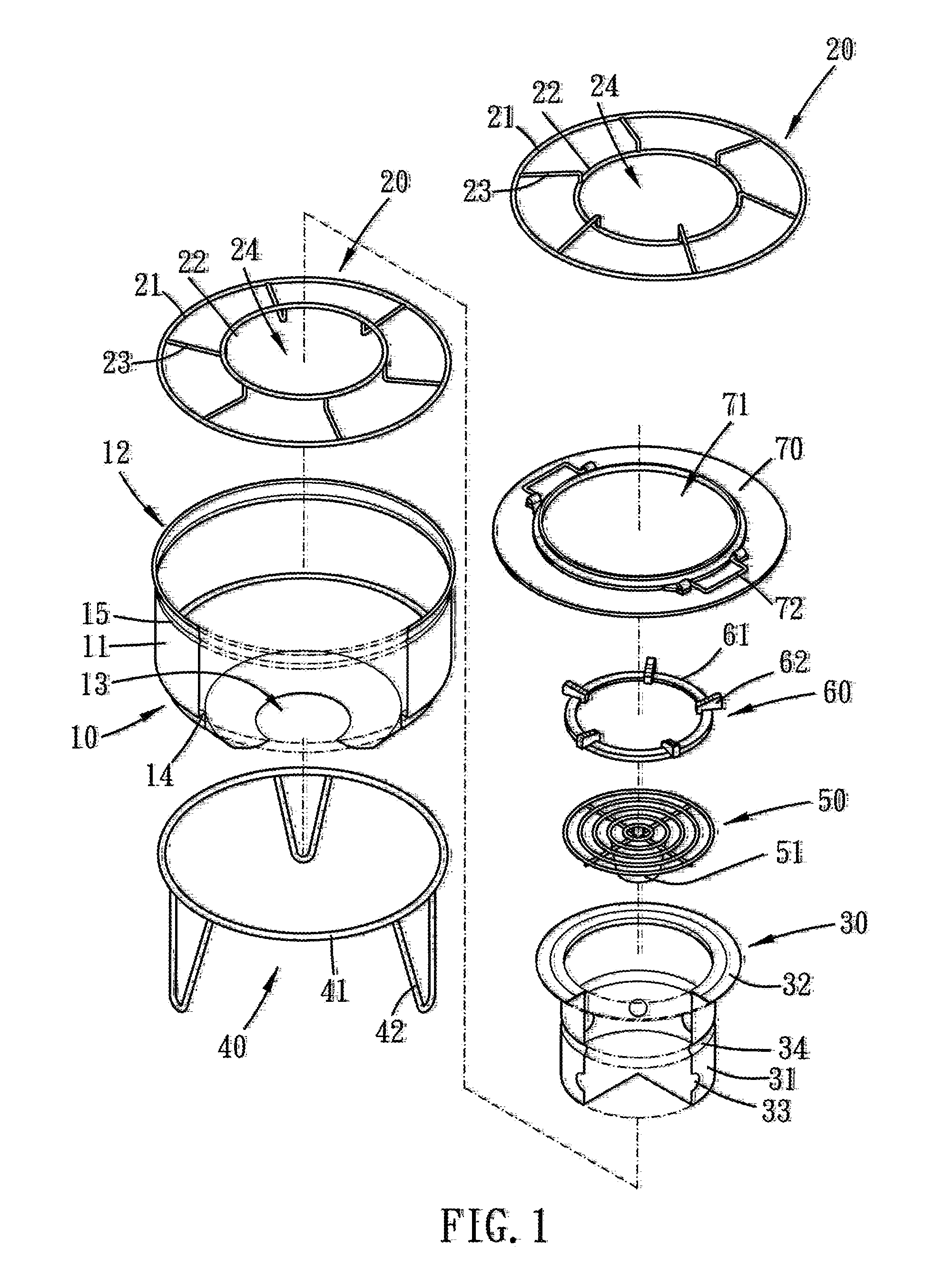
[0027]Please refer to FIG. 1 to FIG. 3 for the present invention. The multi-functional cooking stove includes a stove body 10, a position frame 20, a stove element 30, a base 40, a coal frame 50, a stove rack 60 and an annular cover plate 70.

[0028]The stove body 10 has an annular shell 11 which defines an upper opening 12 and a lower opening 13. The lower opening 13 is smaller than the upper opening 12. The stove body 10 has a lower portion being tapered such that the air flow rate accelerates as the air enters the stove body 10 of bigger cross section via the lower opening 13 of smaller cross section. In addition, a negative pressure of the stove body 10 will draw the air into the stove body 10 to promote its air circulation. In the present embodiment, the tapered lower portion and the vertical upper portion of the stove body 10 is integrally formed, yet they can be separately formed and combined together with fixation means.

[0029]The base 40 is adapted for the stove body 10 to dis...

second embodiment

[0035]Please refer to FIG. 5 and FIG. 6 for the present invention. The cooking stove of the present embodiment also includes the stove body 10, the position frame 20, the stove element 30, the base 40 and the coal frame 50, and it further includes an annular extender 80 which is disposed on the stove body 10 and corresponds to the upper opening 12 to increase the height of the cooking stove for the uniform convection of the heated air. A grill 90 can be disposed atop the annular extender 80 to broil food, and the annular extender 80 may taper off to a bottom thereof as shown in FIG. 13 in order to get an enlarged broiling area.

[0036]Please refer to FIG. 7 and FIG. 8 for the third embodiment of the present invention. Similar to the cooking stoves of the first and second embodiments, the stove of the present embodiment includes the stove body 10, the position frame 20, the stove element 30, the base 40, the coal frame 50, the cover plate 70, the annular extender 80 and the grill 90, y...

fourth embodiment

[0037]Further refer to FIG. 9 and FIG. 10 for the present invention. The cooking stove of the present invention is installed on a table 5 which has a hole 6 and a shield 7 annularly disposed under the hole 6. An engaging rim 8 extends inward from a bottom edge of the shield 7 for the base 40 to mount thereon, so as to install the cooking stove on the table 5 with the stove rack 60 substantially flushing with the table 5. In this case, many users can enjoy cooking at the same time, and the shield 7 can prevent the user from accidentally touching the stove body and get scalded.

[0038]Please refer to FIG. 11. As the user catches fire, the stove element 30 can be taken out of the stove body 10, and the user can fill the cup 51 with alcohol gel or tinder to accelerate the fire catching procedure. Thereafter, the user simply moves the stove element 30 by lifting the position frame 20, as shown in FIG. 12, and installs the stove element 30 in the stove body 10 easily and quickly.

[0039]In su...


PUM


Abstract

A multi-functional cooking stove of the present invention includes a stove body, a position frame and a stove element. The stove body has an annular shell which defines an upper opening and a lower opening. The lower opening is smaller than the upper one. The position frame is disposed in the stove body and defines a through hole at its center for a container body of the stove element to pass therethrough. The stove element is adapted for fuel to dispose therein. A convection space is defined between the stove body and the stove element. At least one convection bore is formed on a periphery of the container body to communicate the convection space with an interior of the container body.

Description

BACKGROUND OF THE INVENTION[0001]1. Field of the Invention[0002]The present invention relates to a cooking stove, and more particularly to a multi-functional cooking stove suitable for many cooking manners.[0003]2. Description of the Prior Art[0004]Barbecue is popular around the world, especially in reunions or outings with family or friends. People can have fun broiling food manually and interacting with each other at the same time.[0005]The conventional cooking stoves, such as the Applicant's TW pat. No. M327704 and M340020, mainly include an annular web partition disposed at the center of the stove and a grill disposed atop the web partition. The Fuel such as charcoal is displaced between the web partition and the stove shell, preventing the grease and barbecue sauce from directly dripping on the charcoal and causing hazard or smoke.[0006]Such conventional cooking stoves are not direct-heating type stove, i.e. the heat source is not located right beneath the food, but they mainly...

Claims


Application Information

Patent Timeline
IPC IPC(8): A47J37/00
CPCA47J37/0704F24B15/005A47J37/079
Inventor CHANG, FREDDIE
Owner AFIRE
Why Eureka
Try Eureka