[0010]With such lighting device, high intensity light may be provided while thermal energy may efficiently be dissipated. Further, with such lighting device a relative homogeneous light distribution (of the light converter light) may be provided (downstream from the CPCs). Further, the thickness or depth of such lighting device may be minimized.
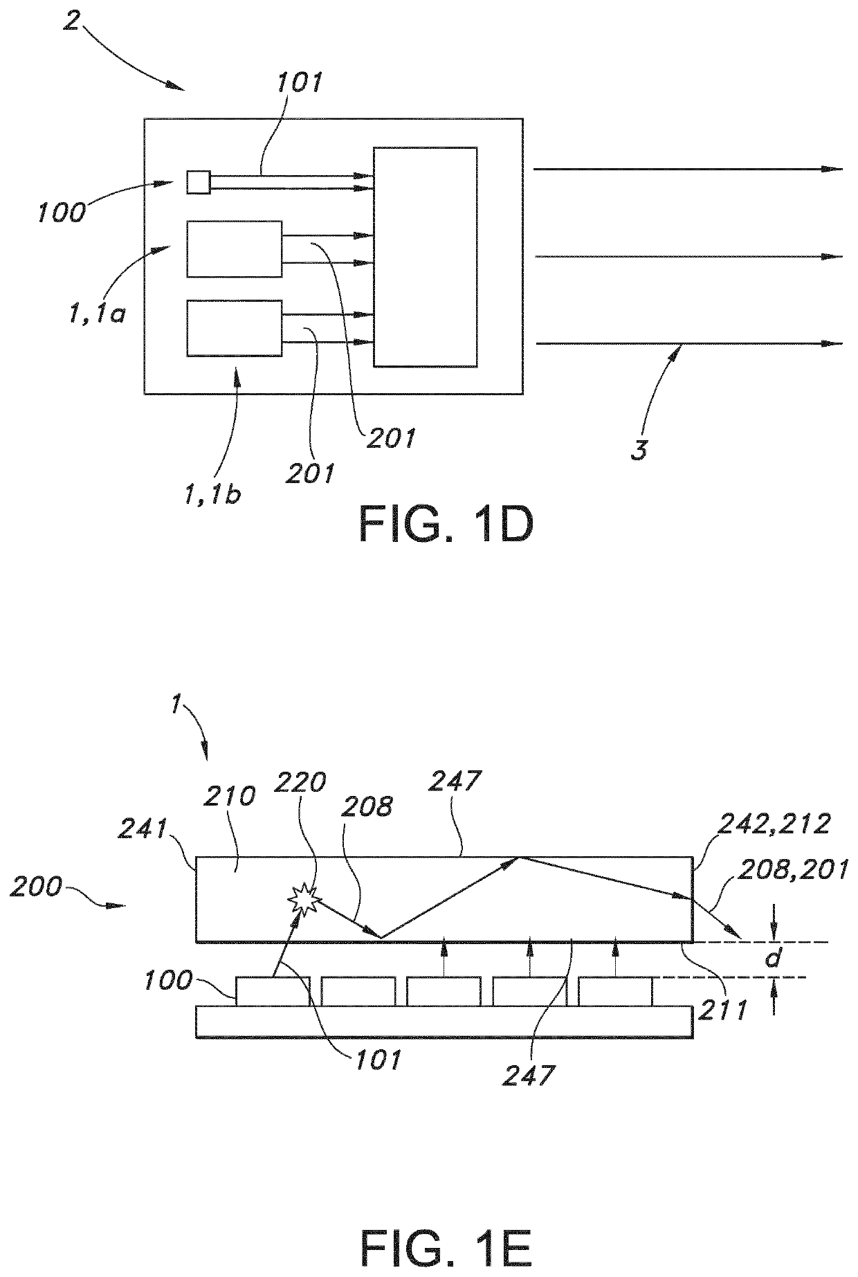
[0011]As indicated above, especially the lighting device comprises a plurality of light sources. The light sources may include laser light sources. Each light converter element may be irradiated with a single light source, such as a laser light source. However, in embodiments one or more light converter element may be irradiated with more than one light source, i.e. a plurality of light sources. Hence, in embodiments the number of light sources may be equal to the number of light converter element; however, in other embodiments the number of light sources is larger than the number of light converter element, such as at least two times larger, like 10 times larger. However, in yet other embodiments two or more light converter elements of a plurality of light converter elements, which plurality of light converter elements are especially arranged in a n×m array (with n and m (independently) both equal to or larger than 2), are irradiated by a single light source, especially a laser. Hence, the device may comprise a number of light sources smaller, equal to or larger than the number of light converter elements, in embodiments especially equal to or larger than the number of light converter elements. Assuming more than one light source, in embodiment the light sources may be controlled with a control system. For instance, in this way light intensity of the light emanating from the device (device light) may be controlled. Optionally, in this way also the beam shape of the light emanating from the device may be controlled.
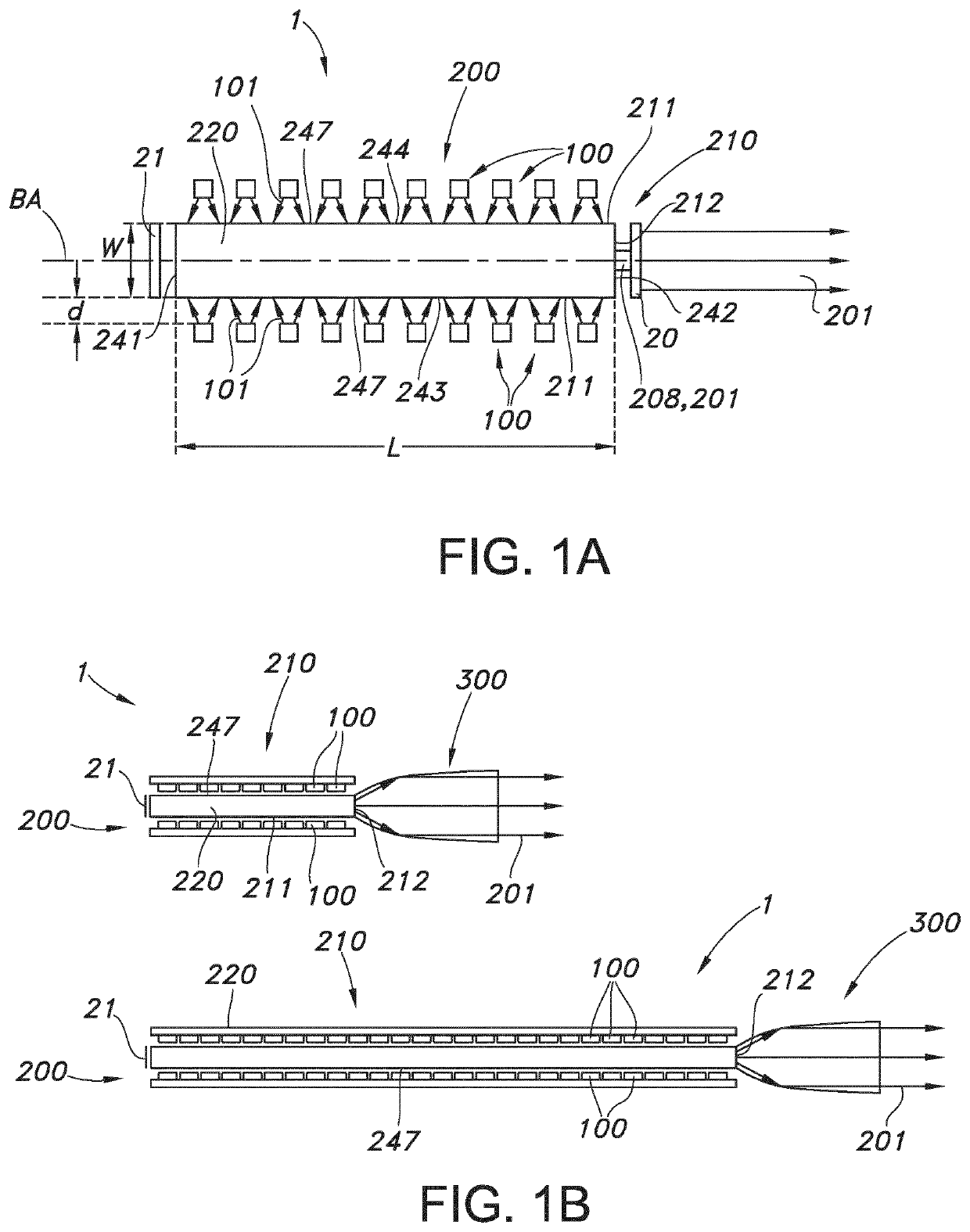
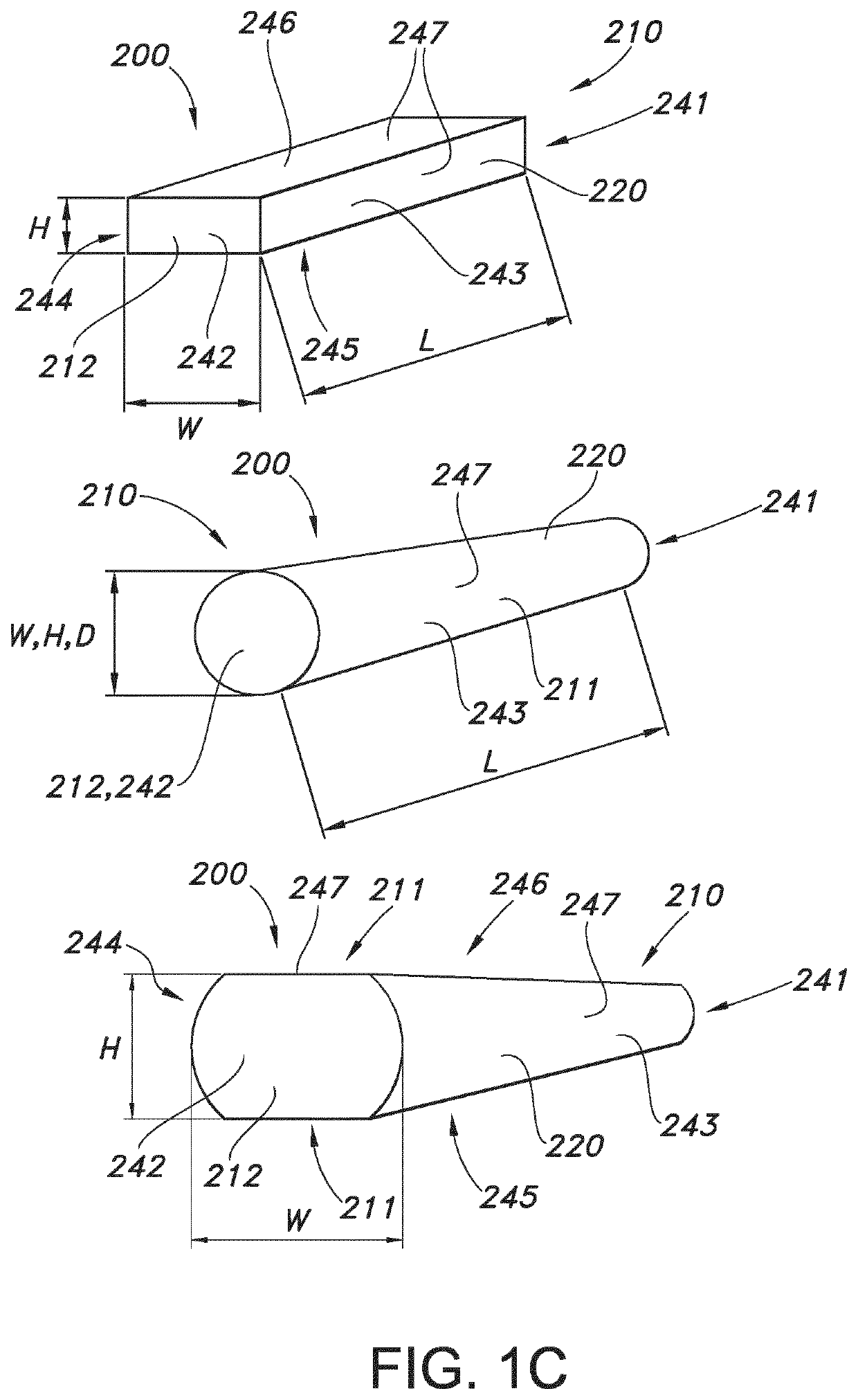
[0031]For thermal management, the light converter elements are in thermal contact with a heat sink. Especially, the thermal contact includes a physical contact. Additionally or alternatively, a thermally conductive material (such as e.g. a silicone glue layer or other thermally conductive adhesive) may be configured between the heat sink and the light converter element. Especially, such intermediate layer has an index of refraction lower than that of the light converting material, such as at least 10%, even more especially at least 20% lower. The heat sink may in embodiments include cavities for hosting part of the light converter element(s). In specific embodiments, each light converter element comprises two or more faces in physical contact with the heat sink. In this way, thermal energy may be dissipated efficiently. In yet further embodiments, the light converter elements comprise elongated luminescent bodies, wherein the heat sink at least partly perimetrically surrounds the light converter elements. Also in this way thermal energy may be dissipated efficiently. In yet other embodiments, the light converter elements comprise plates or disks, with such plates or disks comprising two faces bridged by an edge, wherein an edge height is substantially smaller (such as at least 5 times) than a length and / or a width. Such plate or disk may thus include two (large) faces and an edge, wherein one of the (large) faces is in thermal contact with the heat sink. Optionally, also at least part of the edge may be in thermal contact with the heat sink.
[0044]The light transmissive body as set forth below in embodiments according to the invention may also be folded, bended and / or shaped in the length direction such that the light transmissive body is not a straight, linear bar or rod, but may comprise, for example, a rounded corner in the form of a 90 or 180 degrees bend, a U-shape, a circular or elliptical shape, a loop or a 3-dimensional spiral shape having multiple loops. This provides for a compact light transmissive body of which the total length, along which generally the light is guided, is relatively large, leading to a relatively high lumen output, but can at the same time be arranged into a relatively small space. For example luminescent parts of the light transmissive body may be rigid while transparent parts of the light transmissive body are flexible to provide for the shaping of the light transmissive body along its length direction. The light sources may be placed anywhere along the length of the folded, bended and / or shaped light transmissive body.
[0054]Especially, each light converter element comprises a body axis (BA). In yet further embodiments, the elongated light transmissive body of one or more light converter elements comprise an elongated ceramic body. For instance, luminescent ceramic garnets doped with Ce3+ (trivalent cerium) can be used to convert blue light into light with a longer wavelength, e.g. within the green to red wavelength region, such as in the range of about 500-750 nm. To obtain sufficient absorption and light output in desired directions, it is advantageous to use transparent rods (especially substantially shaped as beams). Such rod can be used as light converter element, concentrating over their length light source light from light sources such as LEDs (light emitting diodes), converting this light source light into converter light and providing at an exit surface a substantial amount of converter light. Lighting devices based on light converter elements may e.g. be of interest for projector applications. For projectors, red and green light converter elements are of interest. Green luminescent rods, based on garnets, can be relatively efficient. Such concentrators are especially based on YAG:Ce (i.e. Y3Al5O12:Ce3+) or LuAG (Lu3Al5O12:Ce3+). ‘Red’ garnets can be made by doping a YAG-garnet with Gd (“YGdAG”). Doping of Gd, however, results in a lower thermal stability (thermal quenching). Red-shifting can also be obtained using a high Ce concentration, with a much smaller penalty for thermal stability.
[0065]Quantum dots are small crystals of semiconducting material generally having a width or diameter of only a few nanometers. When excited by incident light, a quantum dot emits light of a color determined by the size and material of the crystal. Light of a particular color can therefore be produced by adapting the size of the dots. Most known quantum dots with emission in the visible range are based on cadmium selenide (CdSe) with a shell such as cadmium sulfide (CdS) and zinc sulfide (ZnS). Cadmium free quantum dots such as indium phosphode (InP), and copper indium sulfide (CuInS2) and / or silver indium sulfide (AgInS2) can also be used. Quantum dots show very narrow emission band and thus they show saturated colors. Furthermore the emission color can easily be tuned by adapting the size of the quantum dots. Any type of quantum dot known in the art may be used in the present invention. However, it may be preferred for reasons of environmental safety and concern to use cadmium-free quantum dots or at least quantum dots having a very low cadmium content.

