Distillation apparatus

a technology of distillation apparatus and distillation chamber, which is applied in the direction of distillation regulation/control, fractional distillation, separation process, etc., can solve the problems of difficult to flexibly cope with fluid flow fluctuation, difficulty in using separation process modules, and limit in an amount of adjustment, so as to effectively collect thermal energy and effectively collect thermal energy

Active Publication Date: 2017-02-09
KOBE STEEL LTD
View PDF0 Cites 6 Cited by
  • Summary
  • Abstract
  • Description
  • Claims
  • Application Information

AI Technical Summary

Benefits of technology

[0011]An object of the present invention is to provide a distillation apparatus that is, even when first output fluid flowed out from a separator includes a component, direct compression of which is difficult, capable of effectively collecting thermal energy of the first output fluid and capable of effectively collecting the thermal energy of the first output fluid according to fluctuation in a flow rate of the first output fluid.

Problems solved by technology

Therefore, when the first output fluid includes, as the first component, a component, direct compression of which is difficult, (e.g., a component that becomes extremely unstable during high pressure or a component that swells a seal section of the compressor), it is difficult to use the separation process module.
In the distillation apparatus described in Patent Literature 3, although the adjustment of the load of the heat pump is performed, there is a limit in an amount of the adjustment.
In other words, in the distillation apparatus described in Patent Literature 3, it is difficult to flexibly cope with fluctuation in a flow rate of fluid flowed out from a top of a separator.

Method used


Image

  • Distillation apparatus
  • Distillation apparatus
  • Distillation apparatus

Examples


first embodiment

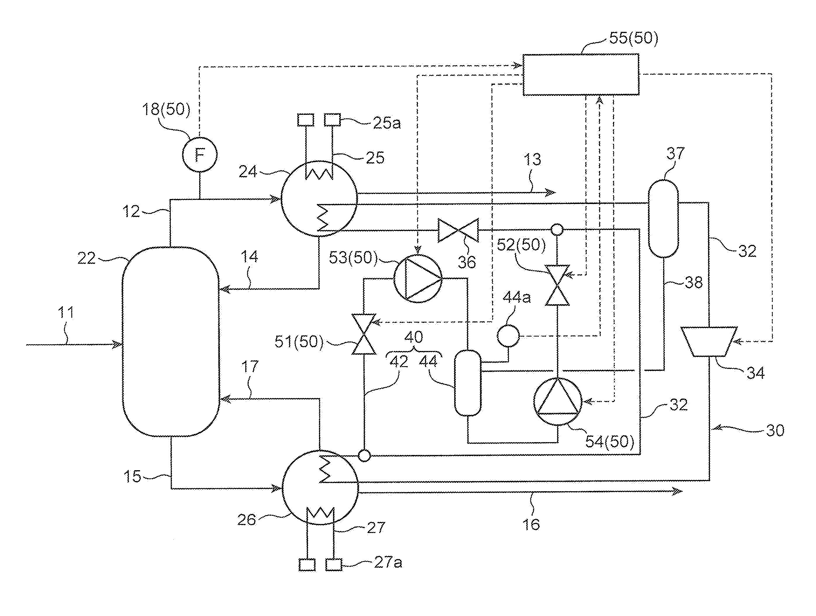
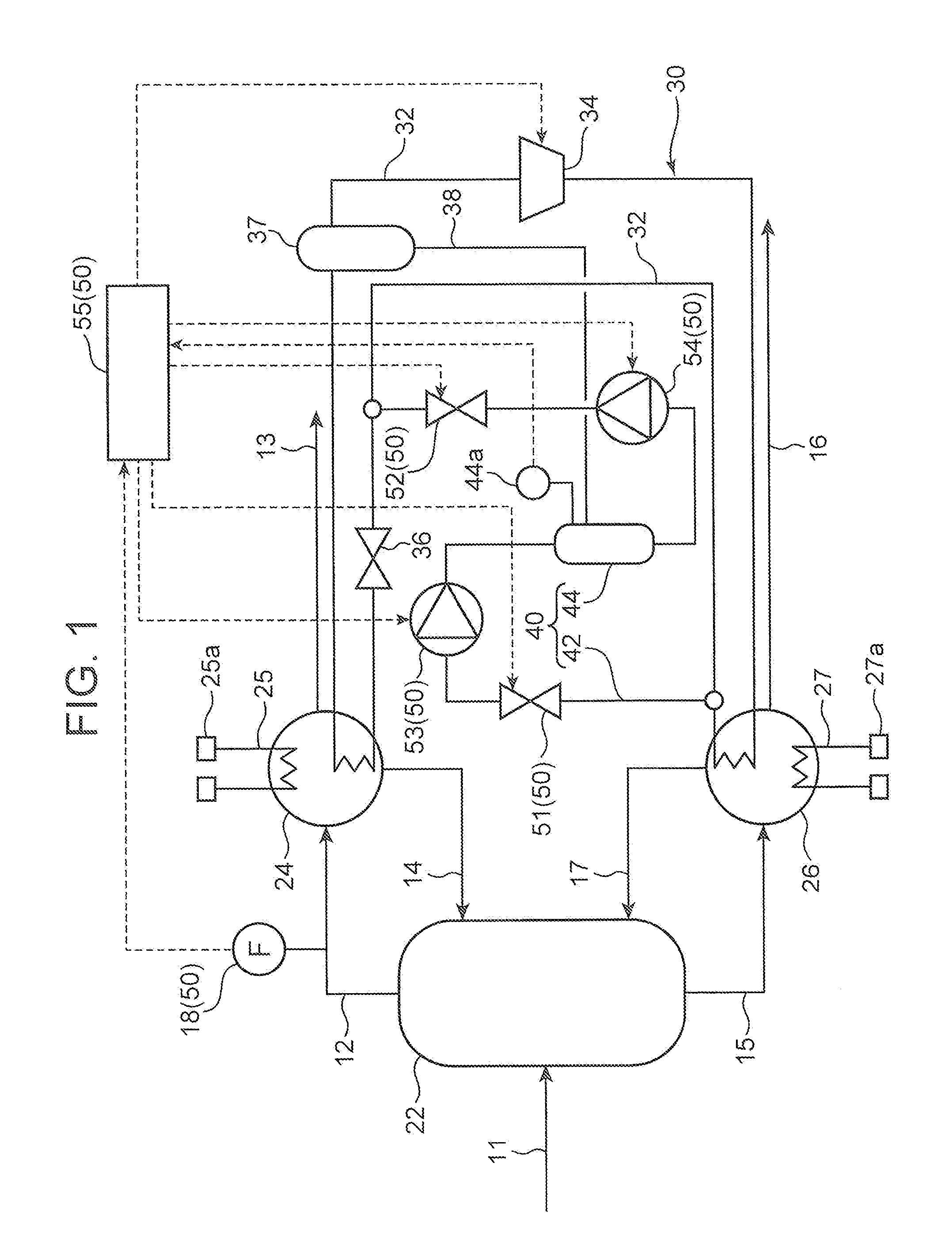
[0019]A distillation apparatus in a first embodiment of the present invention is explained with reference to FIG. 1 and FIG. 2.

[0020]As shown in FIG. 1, the distillation apparatus includes a separator 22, a cooler 24 that cools first output fluid flowed out from the separator 22, a heater 26 that heats second output fluid flowed out from the separator 22, and a heat collection circuit 30. The distillation apparatus is an apparatus capable of indirectly inputting thermal energy of the first output fluid having relatively low temperature to the second output fluid having relatively high temperature via a working medium.

[0021]The separator 22 separates input fluid including a first component and a second component different from the first component into the first output fluid including the first component and the second output fluid including a second component. For example, the first output fluid is distilled stream (distilled liquid) including, as the first component, a lot of compon...

second embodiment

[0058]Next, a distillation apparatus in a second embodiment of the present invention is explained with reference to FIG. 3 to FIG. 5. Note that in the second embodiment, only portions different from the portions in the first embodiment are explained. Explanation of structures, action, and effects same as the structures, the action, and the effect in the first embodiment is omitted.

[0059]In this embodiment, the distillation apparatus further includes a liquid level sensor 24a provided in the cooler 24, a third on-off valve 28 provided in the cooling medium channel 25, a fourth on-off valve 29 provided in the heating medium channel 27, a pressure sensor 32a and a fifth on-off valve 33 provided in the circulation channel 32, and a sixth on-off valve 39 provided in the channel 38 that connects the gas-liquid separator 37 and the tank 44. The liquid level sensor 24a detects a storage amount of the working medium in the liquid state in the cooler 24. The fifth on-off valve 33 is provided ...


PUM


Abstract

A distillation apparatus includes a separator, a cooler, a heater, and a heat collection circuit. The heat collection circuit includes a circulation channel, a compressor, an expanding mechanism, a storing section capable of storing a working medium in a liquid state, and a circulation-amount adjusting section that adjusts a circulation amount of the working medium. The circulation-amount adjusting section adjusts an outflow amount of the working medium, which is stored in the storing section, to the circulation channel or an inflow amount of the working medium, which is circulating in the circulation channel, to the storing section such that the circulation amount increases or decreases according to an increase or a decrease in a flow rate of the first output fluid.

Description

TECHNICAL FIELD[0001]The present invention relates to a distillation apparatus.BACKGROUND ART[0002]There has been known a distillation apparatus that uses a distillation process. For example, Patent Literature 1 discloses a separation process module including a separator, a compressor, a heat exchanger, and a cooler. The separator separates input fluid including a first component and a second component different from the first component into first output fluid including the first component and second output fluid including the second component. The compressor compresses the first output fluid separated by the separator. The heat exchanger causes the first output fluid compressed by the compressor and the second output fluid separated by the separator to perform heat exchange. The cooler cools the first output fluid after performing the heat exchange in the heat exchanger. The first output fluid flowed out from the cooler and the second output fluid flowed out from the heat exchanger...

Claims


Application Information

Patent Timeline
Patent Type & Authority Applications(United States)
IPC IPC(8): B01D3/00B01D3/42B01D3/32
CPCB01D3/007B01D3/42B01D3/32Y02P70/10B01D3/4211
Inventor KISHIMOTO, AKIRATOMARI, KEIICHIROTOSHIMA, MASATAKENISHIMURA, MAKOTO
Owner KOBE STEEL LTD
Why Eureka
Try Eureka