
Polishing abrasive particle, production method therefore, polishing method, polishing device, and slurry

a technology of polishing abrasives and polishing waste, which is applied in the field of polishing abrasives, can solve the problems of deteriorating a working environment, reducing productivity, and exposing abrasive particles and waste generated by polishing to high frictional heat, so as to accelerate the chemical abrasive action, improve the polishing rate, and improve the effect of polishing ra

Active Publication Date: 2016-11-10
ASAHI KASEI KK
View PDF0 Cites 5 Cited by
  • Summary
  • Abstract
  • Description
  • Claims
  • Application Information

AI Technical Summary

Benefits of technology

The present invention provides abrasive particles that have several components integrated with each other using a mechanical alloying process. The biding energy between components is strong, preventing decomposition during the polishing process. The chemical abrasive action induces a mechanochemical effect on the surface of the object material, enabling high polishing rates. A reaction promoter accelerates the chemical abrasive action by reacting to the heat generated in a friction between the object material and the abrasive particle. The polishing process is further improved by the fact that each abrasive particle can exert its own function serially. The abrasive particle can be made rigid or flexible depending on the polishing requirements. The slurry produced by scattering the abrasive particles is almost harmless and easy to treat. The abrasive particles can be used repeatedly, being economical and environmentally friendly. The present invention solves the problem of limited thermal energy utilization in conventional wet polishing methods.

Problems solved by technology

However, the abrasive particles and waste generated due to the polishing have been exposed to the high frictional heat.
Thus, there is the problem that it takes time to clean up the device and therefore the productivity is decreased.
However, the slurry including the oxidizing agent may deteriorate a working environment and increase the liquid-waste treatment cost.
Moreover, the oxidizing agent possibly corrodes the polishing device.
However, the strong alkaline slurry of pH 10 to 14 may deteriorate the working environment and increase the liquid-waste treatment cost.
Anyway, in the above methods, the property of the slurry tends to change during the polishing process.
This necessitates monitoring and adjustment of the process by workers, making an automation of the process impossible.
Accordingly, in the conventional methods, it is difficult to polish SiC or GaN having high corrosion-resistance with high quality, at a practically high polishing rate.

Method used


Image

  • Polishing abrasive particle, production method therefore, polishing method, polishing device, and slurry
  • Polishing abrasive particle, production method therefore, polishing method, polishing device, and slurry
  • Polishing abrasive particle, production method therefore, polishing method, polishing device, and slurry

Examples


first embodiment

[0119]FIG. 4A and FIG. 4B are micrographs of the abrasive particle of the present invention, and FIGS. 4C-4F are explanatory figures of polishing action by the abrasive particle of the present invention.

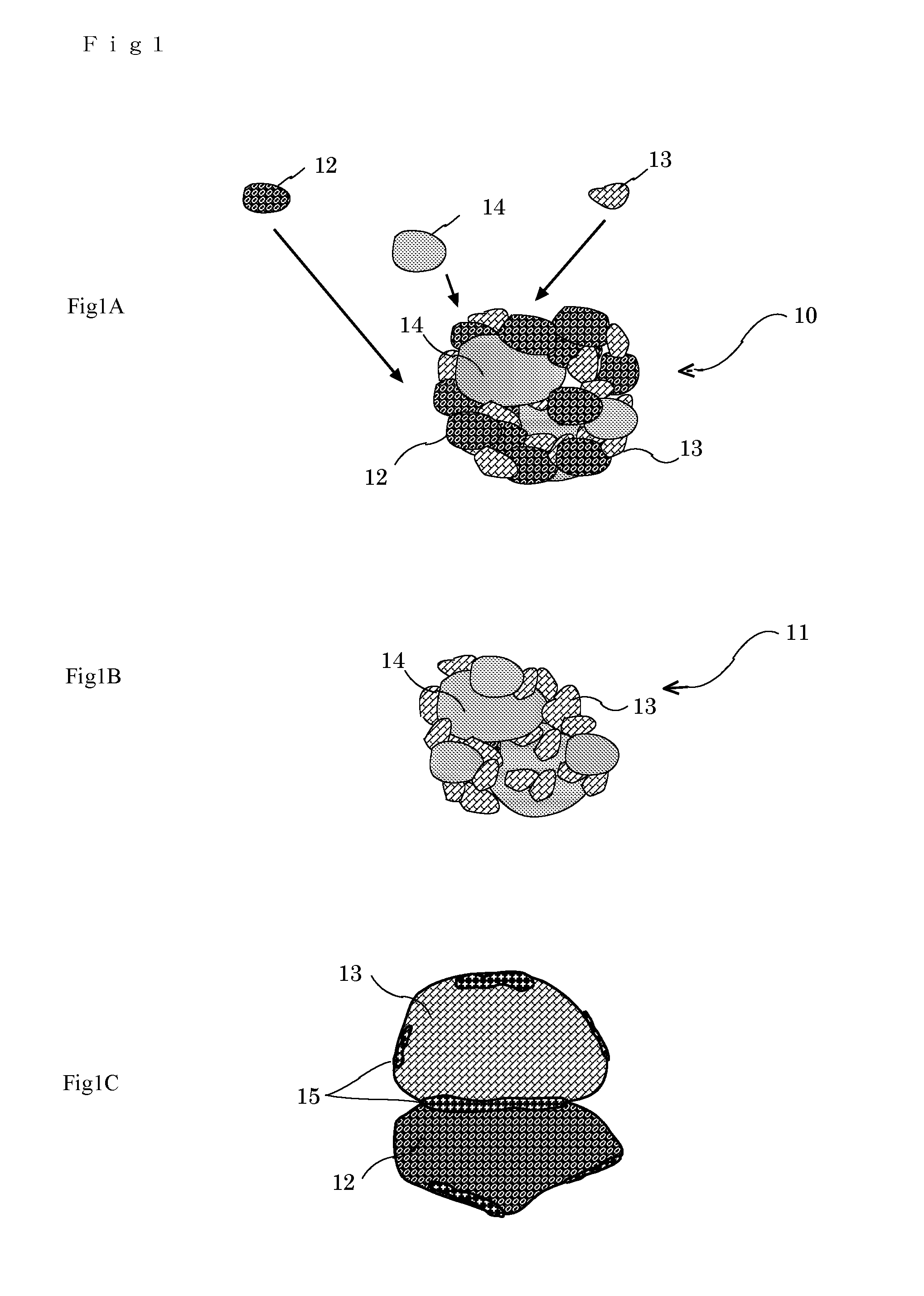
[0120]FIG. 4A is a micrograph which illustrates the abrasive particles of a first embodiment immediately after integrated. As shown in FIG. 4A, various sizes of abrasive particles exist. The average particle size is 5 to 6 μm. The particles having the size of about 1 μm are also included. FIG. 4B is a partial enlarged view of the abrasive particle having outer diameter of about 6 μm in FIG. 4A. Three kinds of components, where each of them is grinded in advance, are mixed and strongly integrated with each other. The components are integrated, while maintaining the inherent chemical and the physical properties respectively. In the abrasive particle of the present embodiment, the components are integrated not so as to be separated from each other even after the polishing process. Even ...

embodiment 2

[0139]FIG. 7 shows a comparison of the polishing rate when various materials are employed as the first component for polishing SiC.

[0140]Sample 1-1 shows, for example, the result when silicon carbide is polished with the abrasive particle in which Al3O3, MnO2 and CaCO3 are integrated.

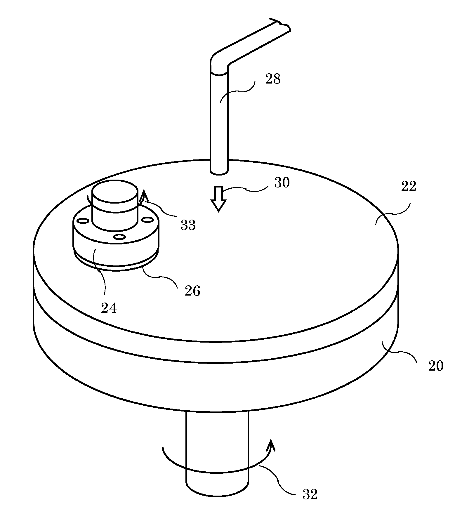
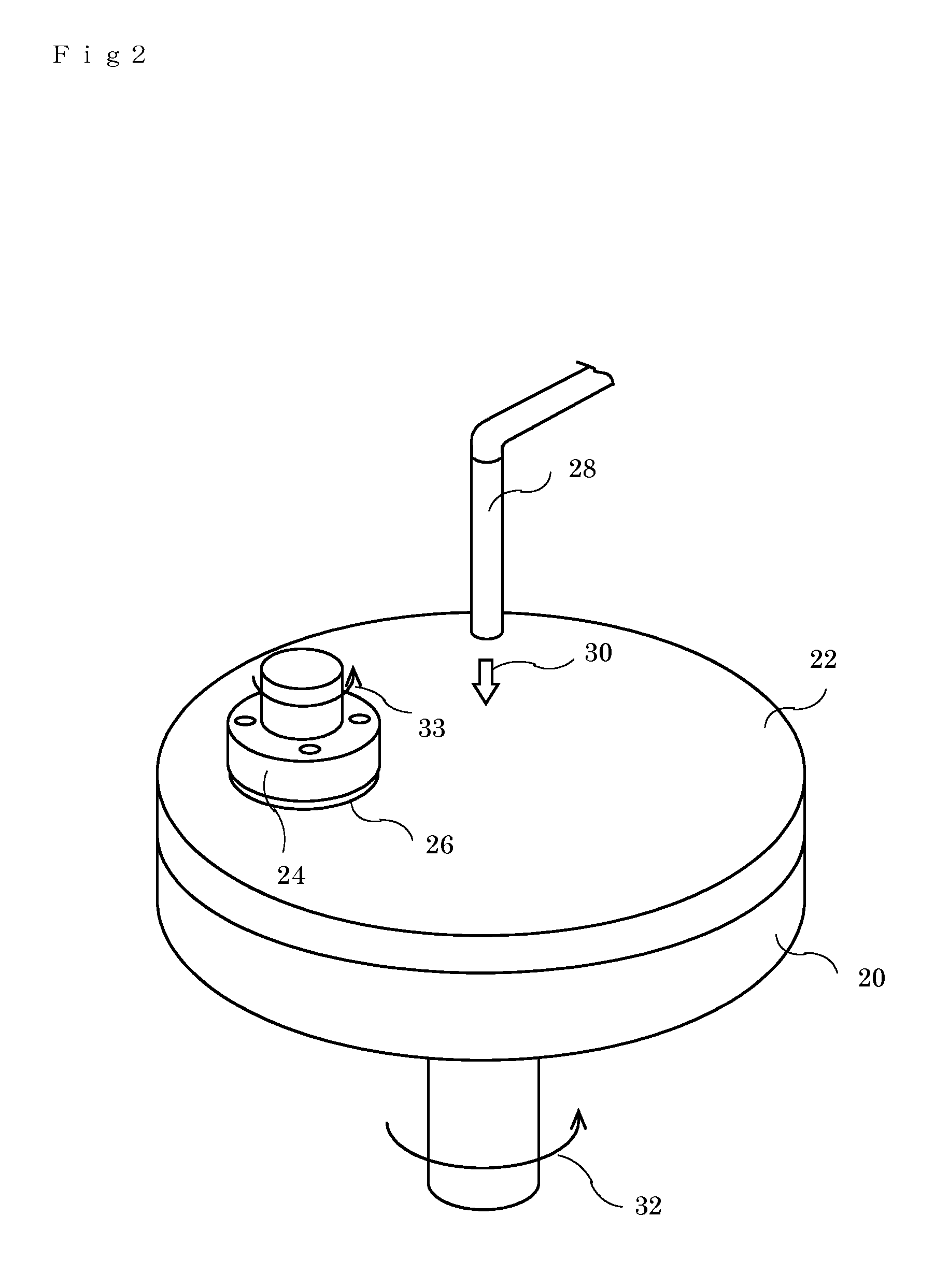
[0141]In this embodiment, the operation condition of the polishing device is set as follows; revolution speed of the surface plate 20 is 5 rpm, revolution speed of holding device 24 is 100 rpm; polishing pressure at which the holding device 24 presses the object material 26 against the surface plate 20 is 160 g / cm2. The slurry produced by scattering of the abrasive particle 15% by weight into pure water is provided on the abrasive pad 22 from the liquid pourer 28 at the rate of 10 ml / min.

[0142]Sample 2-1 shows the result when silicon carbide is polished with the abrasive particle in which ZrO2, MnO2 and CaCO3 are integrated. In each sample, various materials are employed as the first component 12 respec...


PUM

PropertyMeasurementUnit
sizeaaaaaaaaaa
sizeaaaaaaaaaa
temperatureaaaaaaaaaa

Abstract

[Object] The present invention is objected to polish the surface of the object material with a high quality at a high polishing rate.[Solution] The object surface is polished using a wet polishing method. Slurry is produced by scattering abrasive particles into pure water. In the abrasive particle, where components which has a mechanochemical effect and which reacts to the friction heat generated in polishing the object material are joined with each other and integrated to a particle. There, respective component is joined with each other using a mechanical alloying process, while maintaining the inherent material properties. When the slurry is used in a lapping process of sapphire, silicon carbide, gallium nitride and the like, the polishing process can be substantially shortened and the processing cost is drastically reduced. Further, it secures a high quality of the polishing surface. The abrasive particle can be used repeatedly in the polishing process. Since the pH value of the slurry is around 3 to 9, it does not deteriorate working environment and the liquid-waste treatment is easy.

Description

FIELD OF THE INVENTION[0001]The present invention relates to an abrasive particle for polishing a surface of an object material such as sapphire, silicon carbide (SiC), or gallium nitride (GaN). The present invention also relates to a manufacturing method of the above abrasive particle. Further, the present invention also relates to a polishing method, a polishing device, and slurry for polishing.BACKGROUND OF THE INVENTION[0002]In recent years, multifunctional and high-performance semiconductor devices are continuously proposed. In response to the proposals, materials other than silicon (Si) are newly adopted to the substrate of the semiconductor device. Among those substrate materials, sapphire, SiC (for power device), and GaN (for light-emitting diode (LED)) etc. draw special attention to meet the proposals. On the other hands, it is desired to develop new processing methods of substrate, in order to achieve a mass-production of more high-performance devices at low cost.[0003]In ...

Claims


Application Information

Patent Timeline
Patent Type & Authority Applications(United States)
IPC IPC(8): B24B37/24C09K3/14C09G1/02
CPCB24B37/245C09K3/1463C09G1/02B24B37/044C09K3/1472H01L21/02024C09K3/1409H01L21/304H01L21/30625
Inventor FUJIMOTO, SHUNICHIYAMASHITA, TETSUJI
Owner ASAHI KASEI KK
Learn More