Polishing Material Composition And Production Method Therefor

a technology of polishing material and composition, which is applied in the direction of chemistry apparatus and processes, other chemical processes, metal-working apparatus, etc., can solve the problems of high specific gravity of chrome oxide, scratches and scrapes on polished workpieces, and unfavorable dispersion, so as to reduce the surface roughness of polished surfaces, improve the polishing rate and durability, and barely scratch workpieces

Inactive Publication Date: 2015-06-25
KONICA MINOLTA INC
View PDF5 Cites 4 Cited by
  • Summary
  • Abstract
  • Description
  • Claims
  • Application Information

AI Technical Summary

Benefits of technology

[0037]The abrasive composition according to the present invention can achieve a higher polishing rate and durability and barely scratches workpieces and can reduce the surface roughness of the polished surface at a reduced amount of cerium oxide.

Problems solved by technology
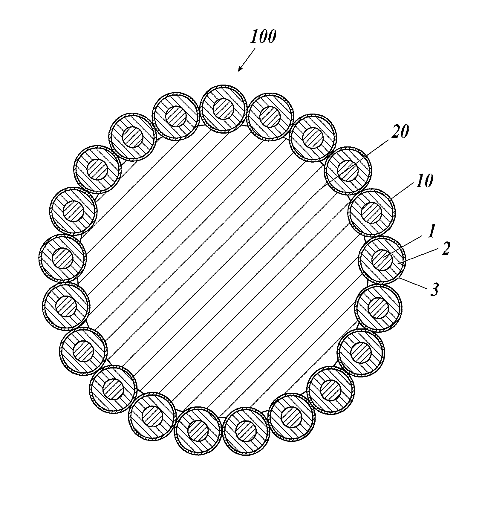
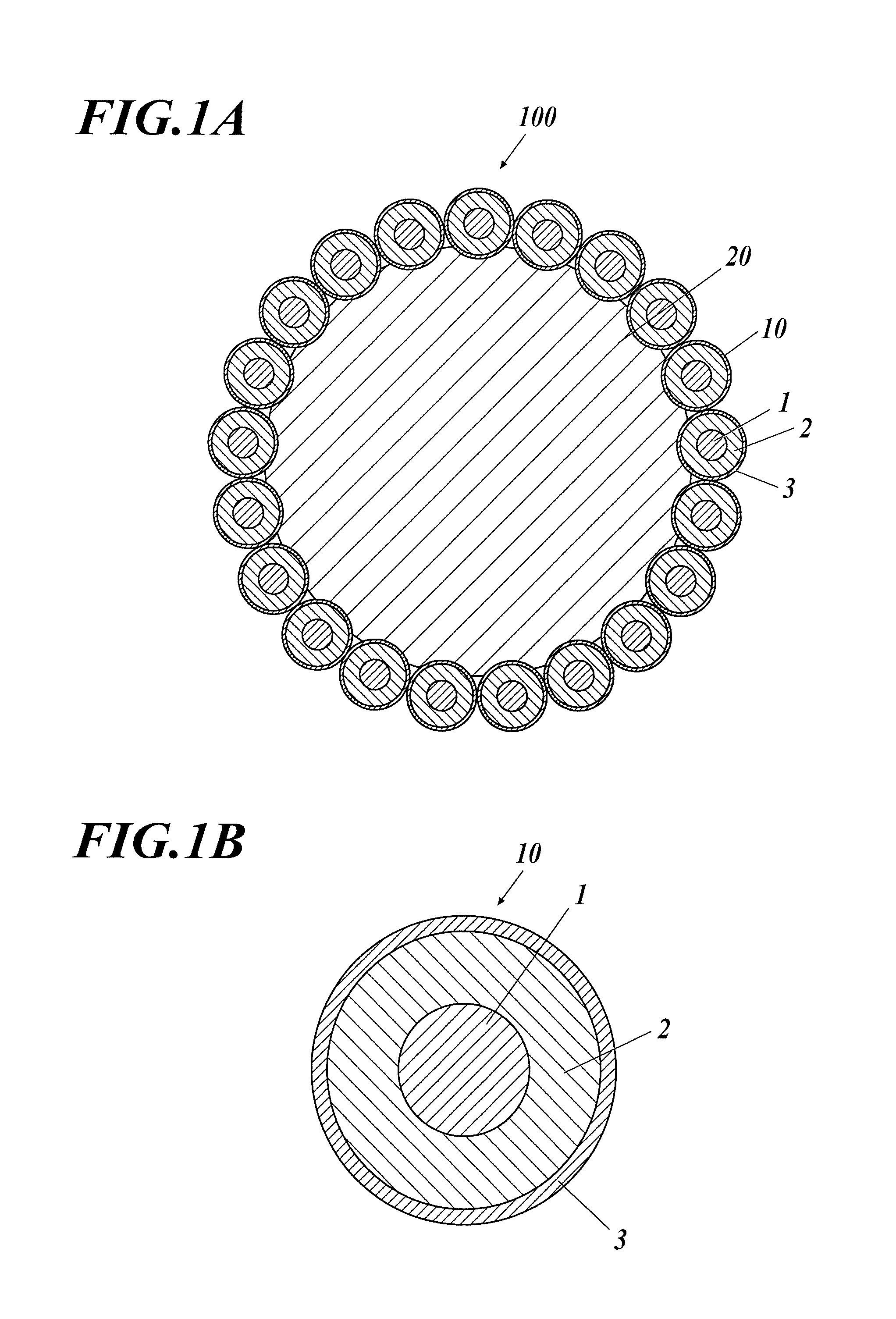
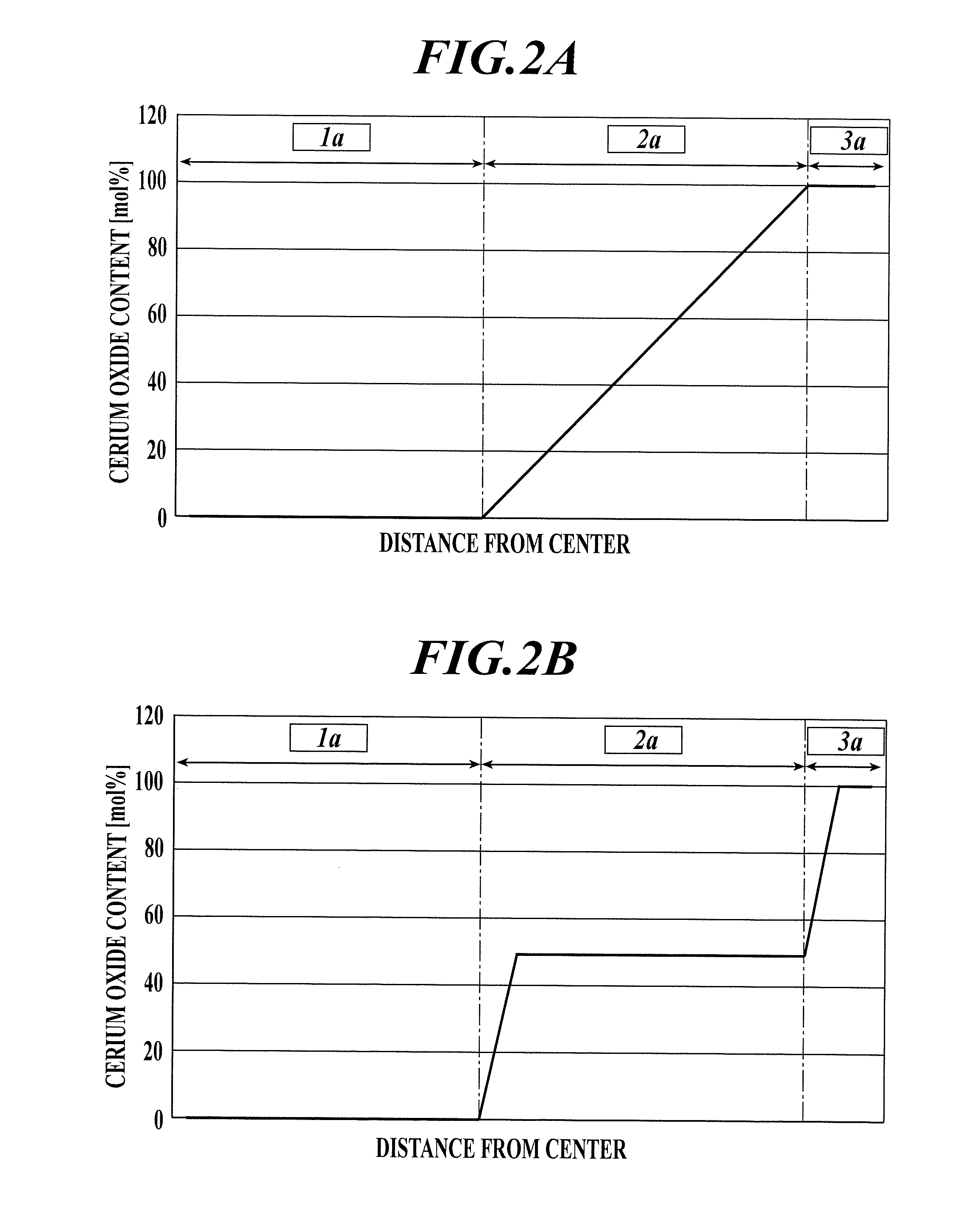
Unfortunately, cerium oxide has high specific gravity and thus has unfavorable dispersion in abrasive slurry.
Furthermore, this compound has high hardness and thus aggregated oxide may cause scratches and scrapes on polished workpieces during polishing.
In addition, cerium oxide is unevenly distributed over the world and is not stably supplied.

Method used


Image

  • Polishing Material Composition And Production Method Therefor
  • Polishing Material Composition And Production Method Therefor
  • Polishing Material Composition And Production Method Therefor

Examples


example 1

Abrasive Material 1

[0082]Step 1. Urea was added to 10 L of aqueous yttrium nitrate (0.01 mol / L) solution into a urea concentration of 0.20 mol / L. The mixture was sufficiently stirred and was then heated at 90° C. for 1 hour with stirring.

[0083]Step 2. A pre-prepared mixture of 300 mL of aqueous yttrium nitrate (0.08 mol / L) solution and 300 mL of aqueous cerium nitrate (0.32 mol / L) solution was added to the dispersion prepared in Step 1 at an addition rate of 10 mL / min with heating at 90° C. and stirring.

[0084]Step 3. 50 mL of aqueous cerium nitrate (0.4 mol / L) solution was added to the dispersion prepared in Step 2 at an addition rate of 10 mL / min with heating at 90° C. and stirring.

[0085]Step 4. The abrasive material precursor precipitated from the dispersion prepared in Step 3 was collected with a membrane filter and was fired at 600° C. to yield inorganic abrasive particles.

[0086]Step 5. To 600 mL of toluene were added 36 g of the inorganic abrasive particles produced in Step 4 a...

example 2

Abrasive Material 2

[0090]Step 1. Urea was added to 10 L of aqueous yttrium nitrate (0.01 mol / L) solution into a urea concentration of 0.20 mol / L. The mixture was sufficiently stirred and was then heated at 90° C. for 1 hour with stirring.

[0091]Step 2. A pre-prepared mixture of 300 mL of aqueous yttrium nitrate (0.08 mol / L) solution and 300 mL of aqueous cerium nitrate (0.32 mol / L) solution was added to the dispersion prepared in Step 1 at an addition rate of 10 mL / min with heating at 90° C. and stirring.

[0092]Step 3. 50 mL of aqueous cerium nitrate (0.4 mol / L) solution was added to the dispersion prepared in Step 2 at an addition rate of 10 mL / min with heating at 90° C. and stirring.

[0093]Step 4. The abrasive material precursor precipitated from the dispersion prepared in Step 3 was collected with a membrane filter and was fired at 600° C. to yield inorganic abrasive particles.

[0094]Step 5. One gram of azobisisobutyronitrile was added to a mixture of 50 mL of styrene and 50 mL of et...


PUM

PropertyMeasurementUnit
particle diameteraaaaaaaaaa
temperatureaaaaaaaaaa

Abstract

An abrasive composition to be used in an abrasive material, including an inorganic abrasive particle. The particle comprises a shell layer being an outermost layer and mainly composed of cerium oxide; and an intermediate layer comprising cerium oxide and an oxide of at least one element selected from the group consisting of Al, Sc, Ti, V, Cr, Mn, Fe, Co, Ni, Cu, Zn, Ga, Ge, Zr, In, Sn, Y, Gd, Tb, Dy, Ho, Er, Tm, Yb, Lu, W, Bi, Th, and alkali earth metals and formed on an inner side of the shell layer. The abrasive composition also includes an organic base member comprising a polymerizable compound, wherein an outer surface of the organic base member is covered with the inorganic abrasive particle.

Description

TECHNICAL FIELD[0001]The present invention relates to an abrasive composition and a method of producing the same.BACKGROUND ART[0002]In precision polishing in process of producing glass optical elements, glass substrates, and semiconductor devices, abrasive materials composed of oxides of rare earth elements, mainly composed of cerium oxide and additionally containing lanthanum oxide, neodymium oxide, praseodymium oxide, and / or oxides of other rare earth elements, have been traditionally used. Although other abrasive materials, for example, diamond, iron oxide, aluminum oxide, zirconium oxide, and colloidal silica are also known, cerium oxide has been widely used from the viewpoint of the high polishing rate and the surface flatness of polished workpieces.[0003]Unfortunately, cerium oxide has high specific gravity and thus has unfavorable dispersion in abrasive slurry. Furthermore, this compound has high hardness and thus aggregated oxide may cause scratches and scrapes on polished ...

Claims


Application Information

Patent Timeline
Patent Type & Authority Applications(United States)
IPC IPC(8): B24D3/28B24D18/00
CPCB24D18/0072B24D3/28C09K3/1436C09K3/1463
Inventor ITO, NATSUKITAKAHASHI, ATSUSHIMAEZAWA, AKIHIRO
Owner KONICA MINOLTA INC
Why Eureka
Try Eureka