
Electronic device

a technology of electronic devices and control circuits, applied in the direction of electroluminescent light sources, ac network voltage adjustment, electric lighting sources, etc., can solve the problems of limited application convenience of leds and increased hardware size of led control circuits, and achieve the effect of convenient utilization and miniaturization

Inactive Publication Date: 2011-04-07
OPTROMAX CORP
View PDF2 Cites 8 Cited by
  • Summary
  • Abstract
  • Description
  • Claims
  • Application Information

AI Technical Summary

Benefits of technology

[0008]The invention is directed to an electronic device, which has advantages of miniaturization and utilization convenience.
[0015]According to the above descriptions, the states of the serial-parallel switch units are switched according to the level variation of the input voltage, so that connection states of the load units are correspondingly changed along with the level variation of the input voltage. In this way, the electronic device can control the load units through AC commercial power without using an embedded AC / DC converter or a transformer. Therefore, compared to the conventional technique, the electronic device of the invention has advantages of miniaturization and utilization convenience.

Problems solved by technology

In other words, the conventional control circuit of the LED is generally embedded with an AC-DC converter or equipped with a transformer so as to control the LED through an AC commercial power, though in this case, not only a hardware size of the control circuit of the LED is increased, but also application convenience of the LED is limited.

Method used


Image

  • Electronic device
  • Electronic device
  • Electronic device

Examples


Embodiment Construction

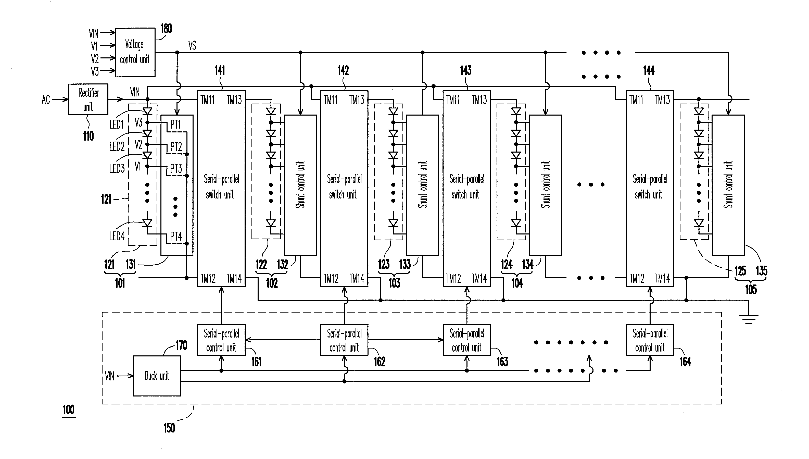
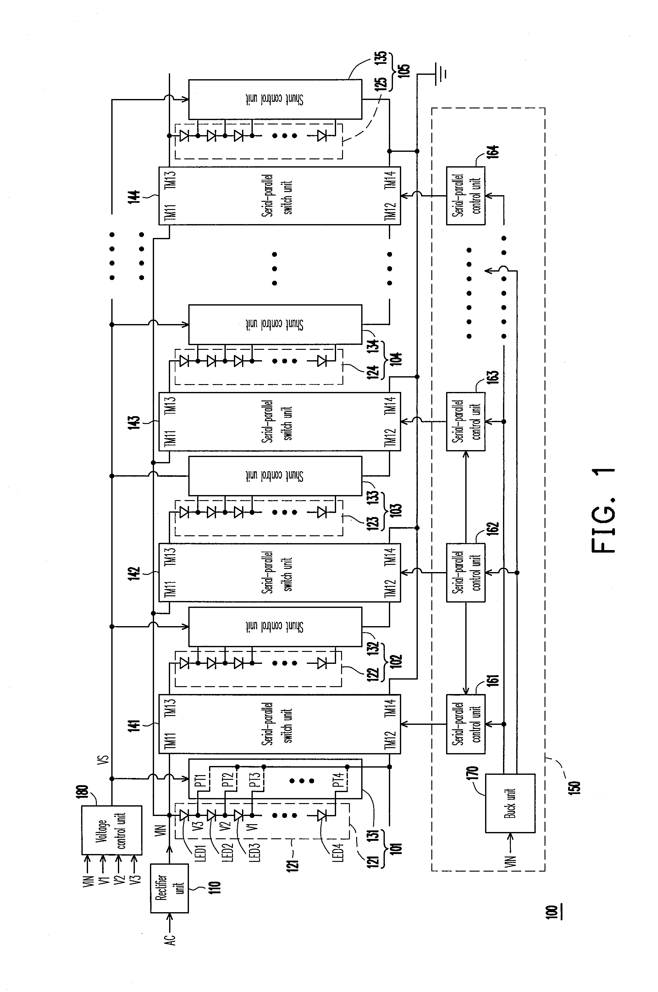
[0028]FIG. 1 is a circuit schematic diagram illustrating an electronic device according to an embodiment of the invention. Referring to FIG. 1, the electronic device 100 includes a rectifier unit 110, N load units 101-105, (N-1) serial-parallel switch units 141-144, and a control module 150, wherein N is an integer greater than 1. The control module 150 includes (N-1) serial-parallel control units 161-164 and a buck unit 170. It should be noticed that the electronic device 100 is an illumination device, in which the load units 101-105 are used to produce light sources. Therefore, in an actual structure, the load units 101-105 respectively include a light emitting diode (LED) string and a shunt control unit, for example, LED strings 121-125 and N shunt control units 131-135. The electronic device 100 further includes a voltage control unit 180, which is used for supplying power required by the shunt control units 131-135 in the load units 101-105.

[0029]Referring to FIG. 1, the rectif...


PUM


Abstract

An electronic device is provided. The electronic device includes a plurality of load units, a plurality of serial-parallel switch units and a control module. The control module switches the serial-parallel switch units to a first state or a second state according to a level variation of an input voltage. Connection relations of the load units are correspondingly changed according to the level variation of the input voltage. In this way, the electronic device can be driven by an alternating-current voltage.

Description

CROSS-REFERENCE TO RELATED APPLICATION[0001]This application claims the priority benefit of Taiwan application serial no. 98133560, filed on Oct. 2, 2009. The entirety of the above-mentioned patent application is hereby incorporated by reference herein and made a part of this specification.BACKGROUND[0002]1. Field of the Invention[0003]The invention relates to an electronic device. Particularly, the invention relates to an electronic device capable of switching load units according to an input voltage.[0004]2. Description of Related Art[0005]Since a light emitting diode (LED) has advantages of long service life, small size, high shock resistance, low heat generation and low power consumption, it is widely used as indicators or light sources in various home appliances and equipments. In recent years, the LEDs are developed to have features of multi-color (multicolor) and high brightness, so that application fields thereof have been extended to large outdoor billboards, traffic lights...

Claims


Application Information

Patent Timeline
Patent Type & Authority Applications(United States)
IPC IPC(8): H05B37/00H02J4/00H05B44/00
CPCH05B33/083H05B33/0827H05B45/48H05B45/46
Inventor CHEN, KUO-TSO
Owner OPTROMAX CORP
Learn More