Electrode pattern for touch screen, driver for touch screen, and touch screen

Inactive Publication Date: 2011-04-07
SAMSUNG ELECTRO MECHANICS CO LTD
View PDF6 Cites 28 Cited by
  • Summary
  • Abstract
  • Description
  • Claims
  • Application Information

AI Technical Summary

Benefits of technology

[0011]An aspect of the present invention provides a touch screen capable of accurately receiving a user selecti

Problems solved by technology

However, in the capacitance type touch screen, noise is generated due to interference between respective driving liens and detection lines, and because the large ITO films are expose

Method used


Image

  • Electrode pattern for touch screen, driver for touch screen, and touch screen
  • Electrode pattern for touch screen, driver for touch screen, and touch screen
  • Electrode pattern for touch screen, driver for touch screen, and touch screen

Examples


Embodiment Construction

[0030]Exemplary embodiments of the present invention will now be described in detail with reference to the accompanying drawings. The invention may, however, be embodied in many different forms and should not be construed as being limited to the embodiments set forth herein. Rather, these embodiments are provided so that this disclosure will be thorough and complete, and will fully convey the scope of the invention to those skilled in the art. In the drawings, the shapes and dimensions may be exaggerated for clarity, and the same reference numerals will be used throughout to designate the same or like components.

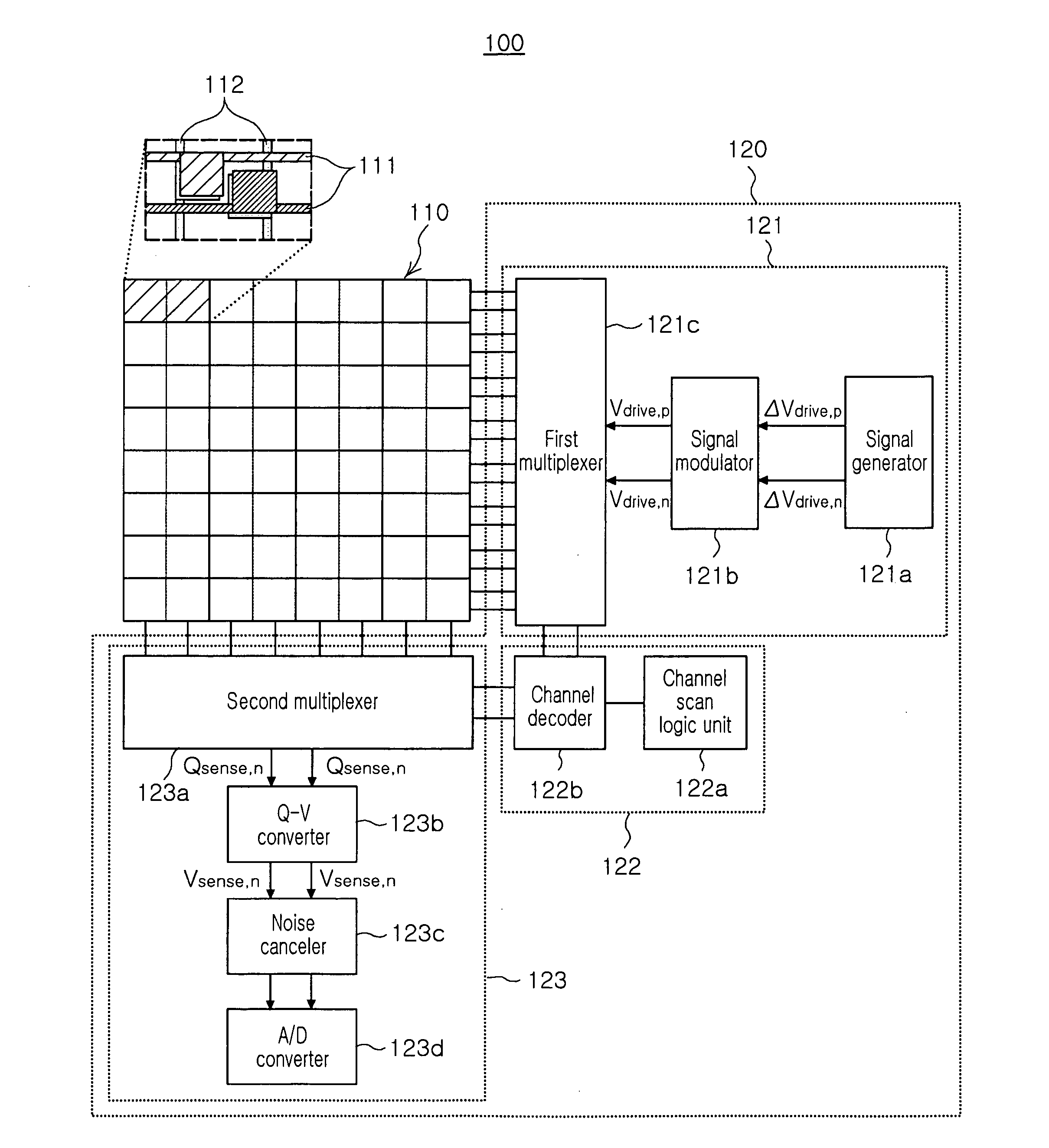
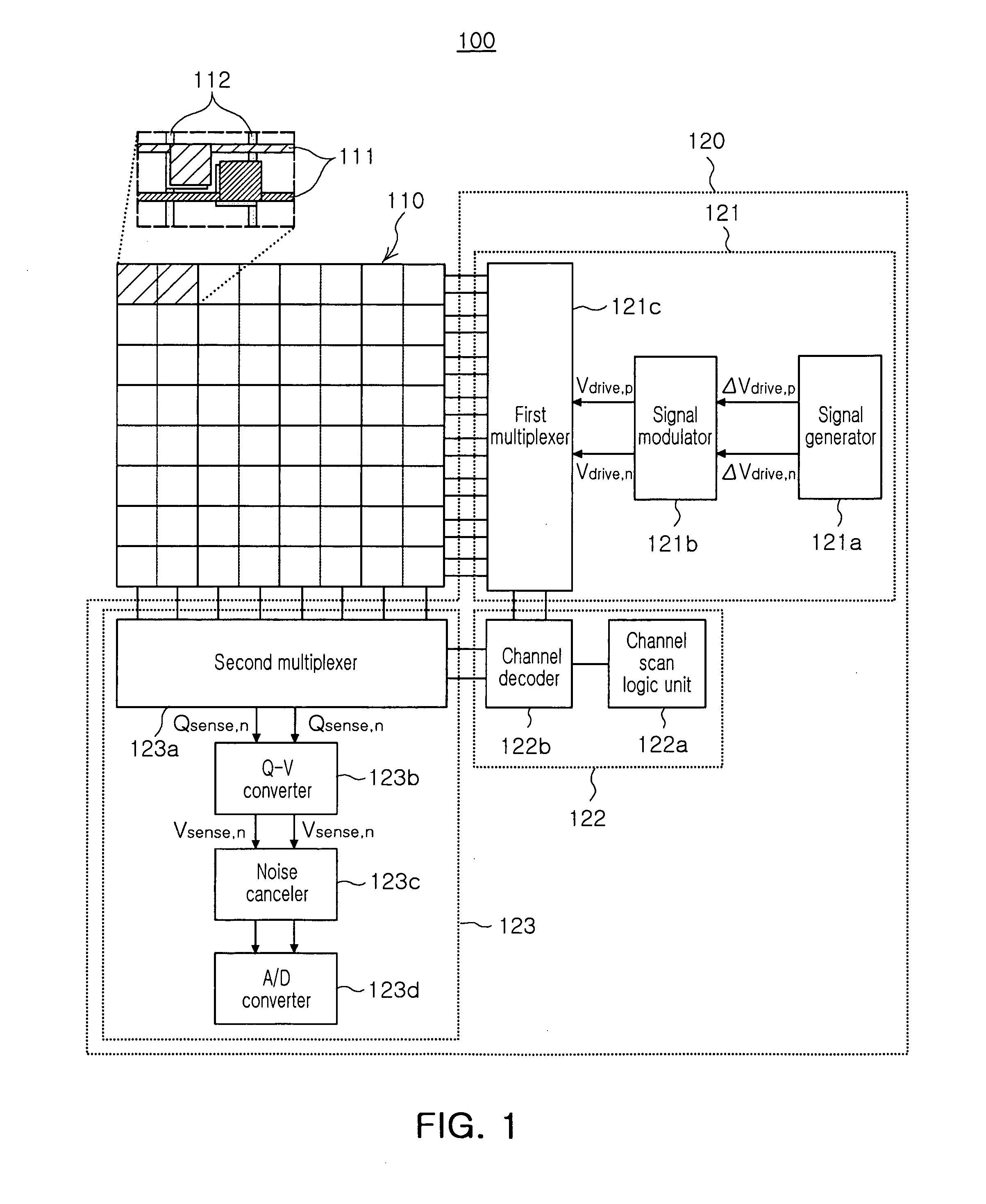
[0031]FIG. 1 is a schematic block diagram showing the configuration of a touch screen according to an exemplary embodiment of the present invention.

[0032]With reference to FIG. 1, a touch screen 100 according to an exemplary embodiment of the present invention may include an electrode pattern 110 and a driving circuit 120.

[0033]The electrode pattern 110 may include first and...


PUM


Abstract

Disclosed is a touch screen to accurately receive a user selection by applying differential signals to the electrode patterns of a touch screen, each having a different capacitance.

Description

CROSS-REFERENCE TO RELATED APPLICATIONS[0001]This application claims the priority of Korean Patent Application No. 10-2009-0095081 filed on Oct. 7, 2009, in the Korean Intellectual Property Office, the disclosure of which is incorporated herein by reference.BACKGROUND OF THE INVENTION[0002]1. Field of the Invention[0003]The present invention relates to a touch screen and, more particularly, to a touch screen capable of accurately receiving a user selection by applying differential signals to electrode patterns of a touch screen, each having a different capacitance.[0004]2. Description of the Related Art[0005]Recently, as electronic devices have become lighter, thinner, shorter, and smaller, a touch screen input scheme having the advantages of allowing for a simple and convenient input procedure tends to be commonly employed for personal information terminals such as PDAs, PMPs, mobile phones, etc., or a banking information terminals such as ATMs.[0006]The touch screen input scheme i...

Claims


Application Information

Patent Timeline
IPC IPC(8): G06F3/041H05K1/00
CPCG06F3/044G06F3/0446G06F3/0354G06F3/0412G06F3/0416G06F3/0445G06F3/0448
Inventor KANG, SHIN JAEKIM, KYUNG UKBAEK, WON JIN
Owner SAMSUNG ELECTRO MECHANICS CO LTD
Why Eureka
Try Eureka