Tangle resistant flexible elongated device

Inactive Publication Date: 2011-04-14
MILLER III JOHN F
View PDF12 Cites 19 Cited by
  • Summary
  • Abstract
  • Description
  • Claims
  • Application Information

AI Technical Summary

Benefits of technology

[0004]In one embodiment, a device is provided that includes a flexible elongated member; and a spiral member. The spiral member is engaged with at least a portion of t

Problems solved by technology

Flexible elongated members such as extension cords, coax, cables, wires, ropes etc. are subj

Method used


Image

  • Tangle resistant flexible elongated device
  • Tangle resistant flexible elongated device
  • Tangle resistant flexible elongated device

Examples


Embodiment Construction

[0014]In the following detailed description, reference is made to the accompanying drawings, which form a part hereof, and in which is shown by way of illustration specific embodiments in which the inventions may be practiced. These embodiments are described in sufficient detail to enable those skilled in the art to practice the invention, and it is to be understood that other embodiments may be utilized and that changes may be made without departing from the spirit and scope of the present invention. The following detailed description is, therefore, not to be taken in a limiting sense, and the scope of the present invention is defined only by the claims and equivalents thereof.

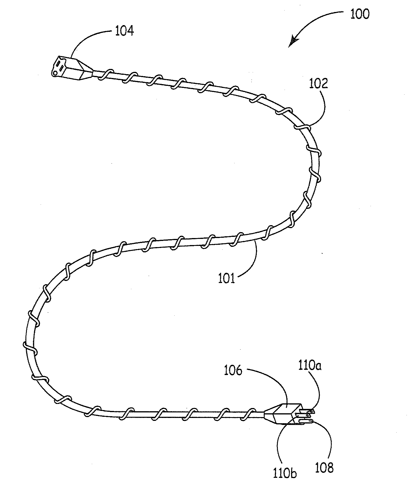
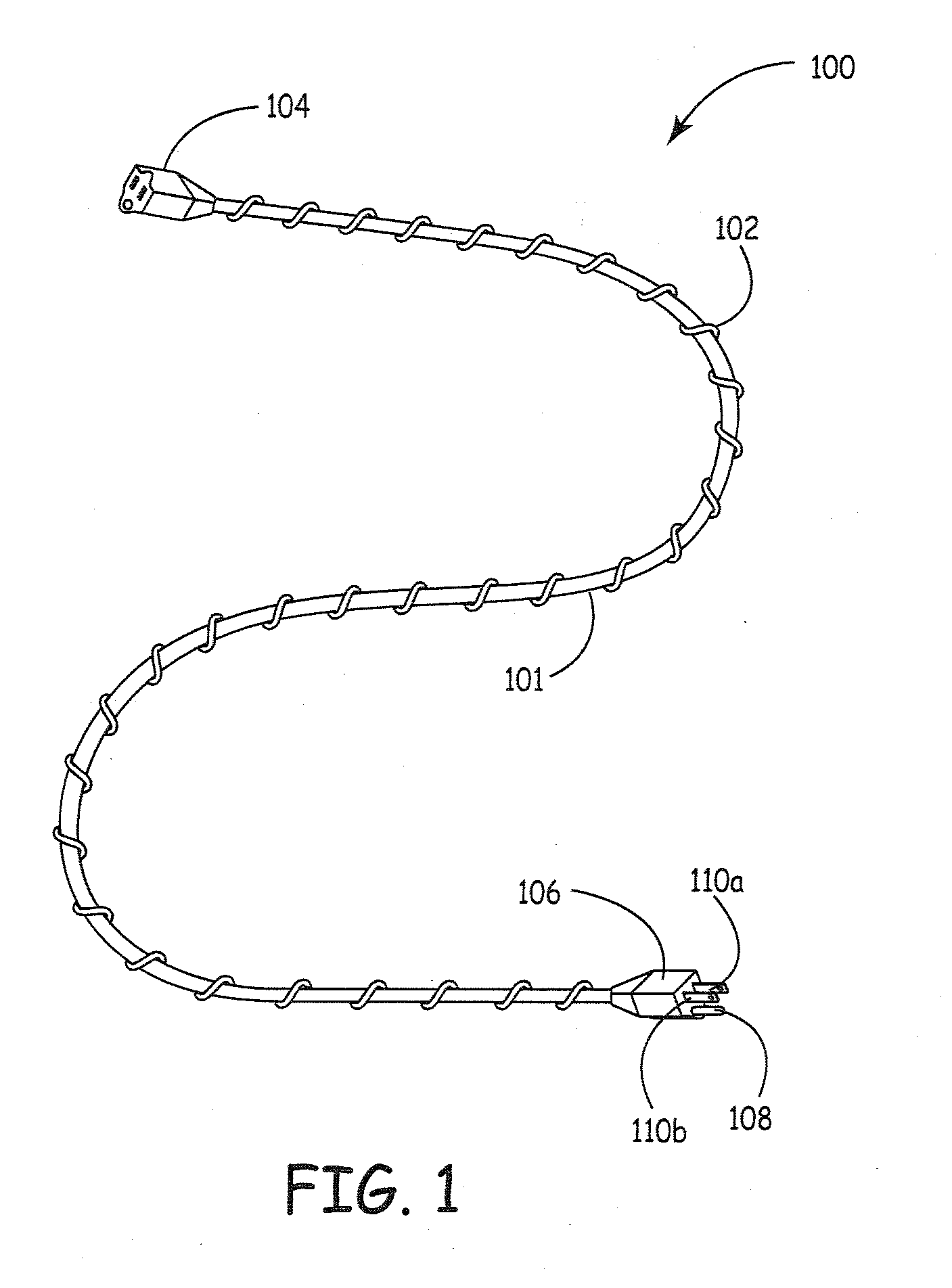
[0015]Embodiments of the present invention provide a flexible elongated member that includes a spiral member that exerts a biasing force on the elongated member to help prevent the elongated member from becoming tangled. Referring to FIG. 1, a top view of a tangle resistant flexible elongated member 100 of an...


PUM


Abstract

A device is provided that includes a flexible elongated member and a spiral member. The spiral member is engaged with at least a portion of the flexible elongated member. The spiral member asserts a biasing force on the flexible elongated member to prevent the flexible elongated member from becoming tangled.

Description

CROSS REFERENCE TO RELATED APPLICATION[0001]This application claims priority from U.S. Provisional Application Ser. No. 61 / 250,215 filed Oct. 9, 2009, the disclosure of which is incorporated by reference.BACKGROUND[0002]Flexible elongated members such as extension cords, coax, cables, wires, ropes etc. are subject to become tangled which can lead to wasted time and frustration on the part of the user. For the reasons stated above and for other reasons stated below which will become apparent to those skilled in the art upon reading and understanding the present specification, there is a need in the art for a relatively tangle resistant flexible elongated device.SUMMARY OF INVENTION[0003]The above-mentioned problems of current systems are addressed by embodiments of the present invention and will be understood by reading and studying the following specification. The following summary is made by way of example and not by way of limitation. It is merely provided to aid the reader in und...

Claims


Application Information

Patent Timeline
IPC IPC(8): H02G3/00F16L55/00D02G3/22
CPCF16L11/081F16L11/10Y10T428/2925H02G11/003H02G3/0481
Inventor MILLER, III, JOHN F.
Owner MILLER III JOHN F
Why Eureka
Try Eureka