Electronic expansion valve

Active Publication Date: 2011-04-14
ZHEJIANG SANHUA INTELLIGENT CONTROLS CO LTD
View PDF8 Cites 25 Cited by
  • Summary
  • Abstract
  • Description
  • Claims
  • Application Information

AI Technical Summary

Benefits of technology

The embodiments of the present invention provide an electronic expansion valve to improve the reliability of the electronic expansion valve.
In the electronic expansion valve according to embodiments of the present invention, by arranging the washer into the annular groove positioned at the lower end of the leading screw in the circumferential direction, with the thickness of the washer being less than the width of the annular groove, and by arranging the spring between the valve needle and the washer, the washer is enabled to rotate around the annular groove in the circumferential direction, and move up and down within the annular groove. After the valve needle leaves the valve port, the washer is pressed onto the valve needle sleeve under the pressure of the spring, and this pressure is only applied to the valve needle sleeve and valve needle 6, while the leading screw is free from it. Thus, the valve needle can be easily adjusted and restored when being displaced, and the valve needle and the leading screw can move relative to each other flexibly. Moreover, when the valve port contacts with the valve needle, the friction surfaces between the leading screw and the washer and between the valve needle sleeve and the washer are small, and the arm of the friction force is also small, so that the leading screw can rotate relative to the valve needle by overcoming a relatively small moment of frictional resistance, which can reduce the starting voltage for the product effectively. Thus the reliability of the electronic expansion valve is improved.

Problems solved by technology

Because of the large spring pressure between the leading screw and the valve needle, when the valve needle having left the valve port deviates relative to the leading screw, the valve needle thus deviated cannot easily be adjusted and restored under the action of the spring pressure.
Moreover, when the valve port contacts with the valve needle, the friction surfaces between the leading screw and the washer and between the valve needle sleeve and the washer are large, and the arm of the friction force is also large, so that the leading screw can only rotate relative to the valve needle by overcoming a relatively large friction resistance, leading to difficulty in the relative rotation between the valve needle and the leading screw.
Therefore, the prior art electronic expansion valve has poor reliability.

Method used


Image

  • Electronic expansion valve
  • Electronic expansion valve
  • Electronic expansion valve

Examples


Embodiment Construction

To clarify the objects, technical solutions and advantages of the embodiments of the present invention, descriptions will be given clearly and sufficiently hereinafter to the technical solutions in the embodiments of the present invention with reference to the accompanied drawings. Apparently, the embodiments described are only a part the invention, not all of it. All other embodiments, which are obtained by those skilled in the art based on the embodiments in the present invention without any inventive effort, are intended to be within the scope of protection of the invention.

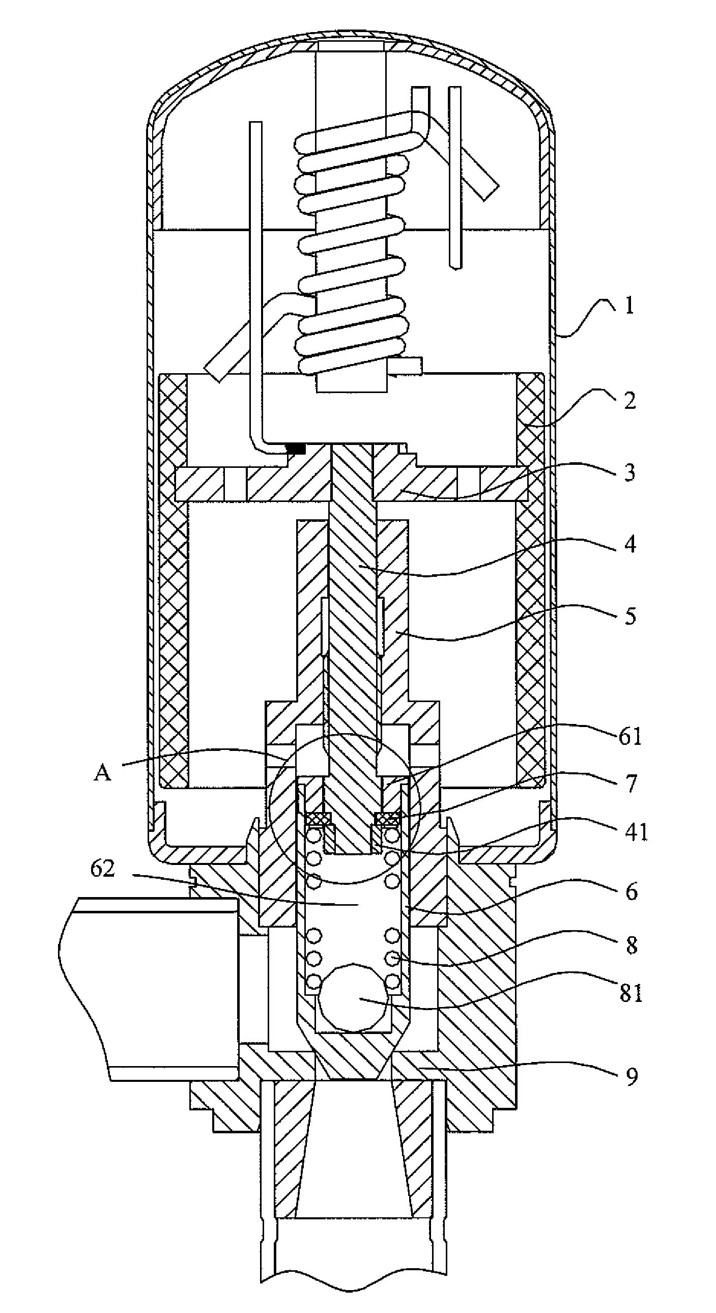
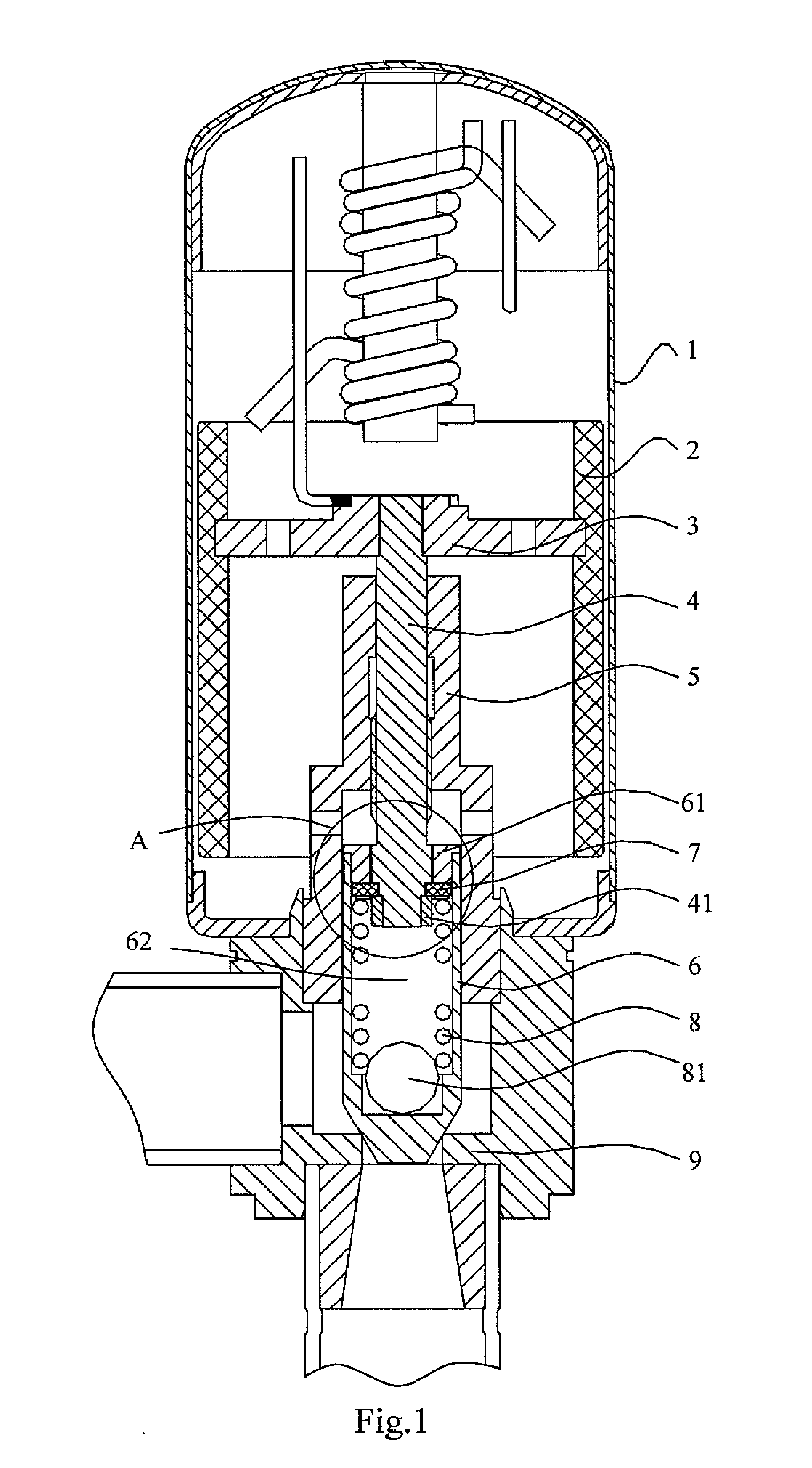
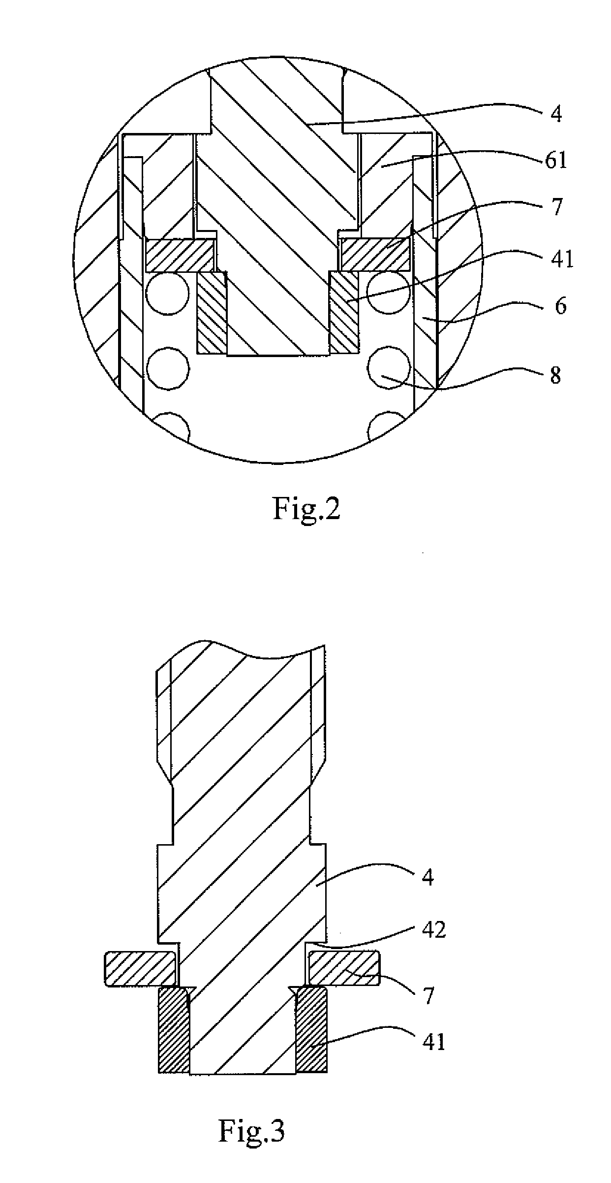
FIG. 1 is a schematic view showing the structure of a first embodiment of an electronic expansion valve according to the present invention, FIG. 2 is a schematic view showing the structure of region A in FIG. 1, and FIG. 3 is a schematic view showing the leading screw and the washer of the first embodiment of the electronic expansion valve in assembly according to the present invention. As shown in FIGS. 1, 2 ...


PUM


Abstract

The present invention provides an electronic expansion valve, comprising a leading screw, a valve needle and a valve needle sleeve. It further comprises: a washer provided in an annular groove, which is provided at the lower end of the leading screw in the circumferential direction, and a thickness of the washer is less than a width of the annular groove; the valve needle sleeve abuts against the upper surface of the washer and is fixedly connected with the valve needle; and a spring is provided between the washer and the valve needle. By arranging the washer in the annular groove provided at the lower end of the leading screw in the circumferential direction, with the thickness of the washer being less than the width of the annular groove, and by arranging the spring between the valve needle and the washer, the washer is enabled to rotate around the annular groove in the circumferential direction and move up and down in the annular groove, improving the reliability of the electronic expansion valve.

Description

FIELD OF THE INVENTIONThe embodiments of the present invention relate to valve field, in particular to an electronic expansion valve.BACKGROUNDIn the prior art electronic expansion valve, utilizing the operating principle of a step motor, a magnetic rotor is driven to rotate by a coil, and the rotation of the magnetic rotor is transferred into an up-down movement of a leading screw, which drives a valve needle connected thereto to move upward or downward, thus the flow of the electronic expansion valve can be controlled.The prior art electronic expansion valve has a main structure including a jacket, a valve seat, a magnetic rotor, a nut, a leading screw, a valve needle and a valve needle sleeve, etc. The leading screw is mated with a folding edge on the upper end of the valve needle sleeve by a fixing plate provided on the leading screw, so that the leading screw is movably connected with the valve needle sleeve; and the valve needle sleeve is fixedly provided with a valve needle a...

Claims


Application Information

Patent Timeline
IPC IPC(8): F16K31/02
CPCF25B41/062Y02B30/72F25B2341/065Y02B30/70F25B41/34F25B41/35
Inventor ZHAN, CAIYIYUAN, ZEWEI, XIANRANG
Owner ZHEJIANG SANHUA INTELLIGENT CONTROLS CO LTD
Why Eureka
Try Eureka