Self-restrained pipe joint system and method of assembly

a self-restraining and pipe joint technology, applied in the field of connection, can solve the problems of time-consuming, non-standard mechanical joint bells, and inability to apply self-restraining gaskets, and achieve the effect of discouraging fluid leakag

Active Publication Date: 2011-04-14
MUELLER INT LLC
View PDF99 Cites 39 Cited by
  • Summary
  • Abstract
  • Description
  • Claims
  • Application Information

AI Technical Summary

Problems solved by technology

A challenge is to make the assembly of the pipe joints as simple, economical, and reliable as possible.
Such attempts often require modification of the bell or the gland fitting (or both).
However, these solutions cannot be applied to the existing standardized mechanical joint bells.
However, the assembly of these modified MJ connections still involves in-field installation of the gland, gasket, bolts, and nuts, which can be time consuming.
These self-restraining gaskets, however, cannot be used with the standard bells for MJ connection because of their specific shape and rib requirement.

Method used


Image

  • Self-restrained pipe joint system and method of assembly
  • Self-restrained pipe joint system and method of assembly
  • Self-restrained pipe joint system and method of assembly

Examples


Embodiment Construction

[0026]Embodiments of the present invention now will be described more fully hereinafter with reference to the accompanying drawings, in which some, but not all embodiments of the inventions are shown. Indeed, these inventions may be embodied in many different forms and should not be construed as limited to the embodiments set forth herein; rather, these embodiments are provided so that this disclosure will satisfy applicable legal requirements. Like numbers refer to like elements throughout.

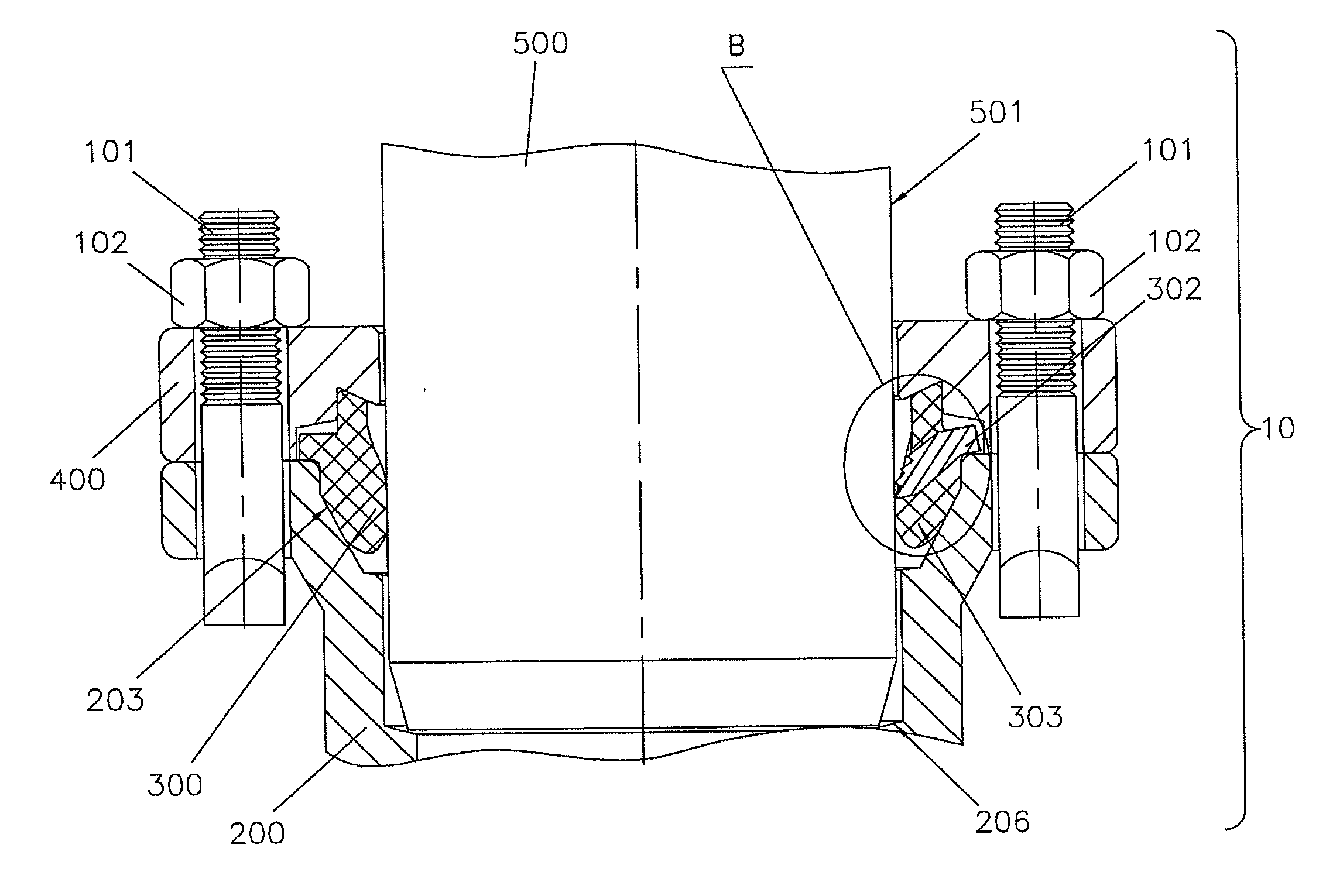
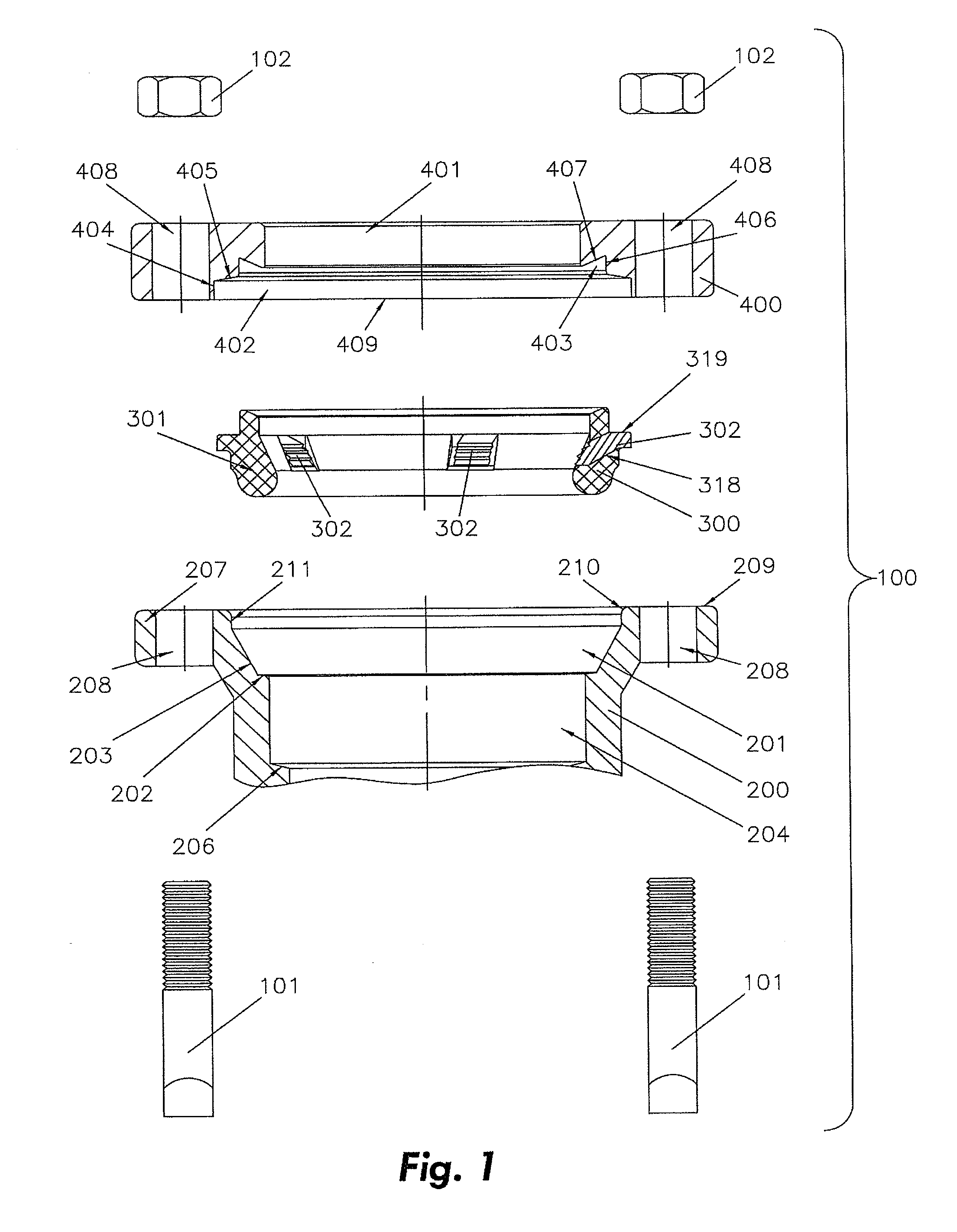
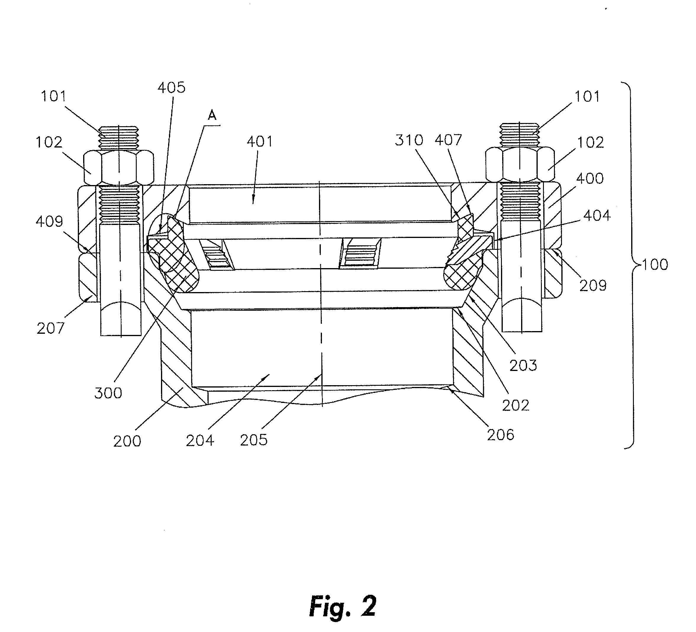
[0027]The pipe joint system and method of assembly embodiments of the present invention will be primarily described in conjunction with pipe joints suitable for round cross-section fluid pipelines. It should be understood, however, that the pipe joint system and method of assembly embodiments of the present invention can be used in conjunction with a variety of other applications, both in fluid pipe conduits and other types of pipelines. For example, the pipe joint system and assembly method embo...


PUM

PropertyMeasurementUnit
angleaaaaaaaaaa
outer diameteraaaaaaaaaa
diameteraaaaaaaaaa

Abstract

A self-restrained pipe joint system and method of assembly to connect two lengths of pipe in a mechanical joint, which maximizes the advantages of both restrained push-on joints as well as mechanical joints, as are known commonly in the art. The invention has application to long-run pipe lengths as well as to appurtenances, including fittings and connections. The gasket contains locking members that act to restrain separation upon the instance of any force tending to separate the connected pipe lengths.

Description

CROSS-REFERENCE TO RELATED APPLICATIONS[0001]This application claims priority to U.S. Provisional Patent Application No. 61 / 250,742 filed Oct. 12, 2009, which is hereby incorporated in its entirety by reference.FIELD OF THE INVENTION[0002]The present invention relates generally to the field of connections between lengths of pipe, or between pipes and fittings. More particularly, this invention is directed towards self-restrained sealing systems and methods of connecting two sections of pipe or pipe and piping appurtenances such as valves, fittings, hydrants and the like.BACKGROUND OF THE INVENTION[0003]The construction of pipelines generally involves the axial connection of two lengths of pipe to form a single pipeline conduit for transporting materials from one point to another. Along the pipeline there may be one or more fittings, which allow the pipe pieces to be joined to other components in the pipeline. The materials usually conveyed via pipelines require that pipeline conduit...

Claims


Application Information

Patent Timeline
Patent Type & Authority Applications(United States)
IPC IPC(8): F16L21/02F16L23/00B23P11/00
CPCY10T29/4995F16L37/0845F16L17/025F16L19/045F16L21/04F16L21/08Y10T29/49872
Inventor GERMAN, MIKHAILFLEURY, LEO
Owner MUELLER INT LLC
Why Eureka
Try Eureka