Training target for an electronically controlled weapon

a technology of electronic control and training target, which is applied in the field of training target for a taser® type gun or weapon, can solve the problem of not intended summary

Inactive Publication Date: 2011-04-21
ODORISIO TIM
View PDF5 Cites 4 Cited by
  • Summary
  • Abstract
  • Description
  • Claims
  • Application Information

AI Technical Summary

Problems solved by technology

Moreover, this Summary is not intended for use as an aid in determining the scope of the claimed subject matter.

Method used


Image

  • Training target for an electronically controlled weapon
  • Training target for an electronically controlled weapon
  • Training target for an electronically controlled weapon

Examples


Embodiment Construction

[0023]Embodiments are described more fully below with reference to the accompanying figures, which form a part hereof and show, by way of illustration, specific exemplary embodiments. These embodiments are disclosed in sufficient detail to enable those skilled in the art to practice the invention. However, embodiments may be implemented in many different forms and should not be construed as being limited to the embodiments set forth herein. The following detailed description is, therefore, not to be taken in a limiting sense in that the scope of the present invention is defined only by the appended claims.

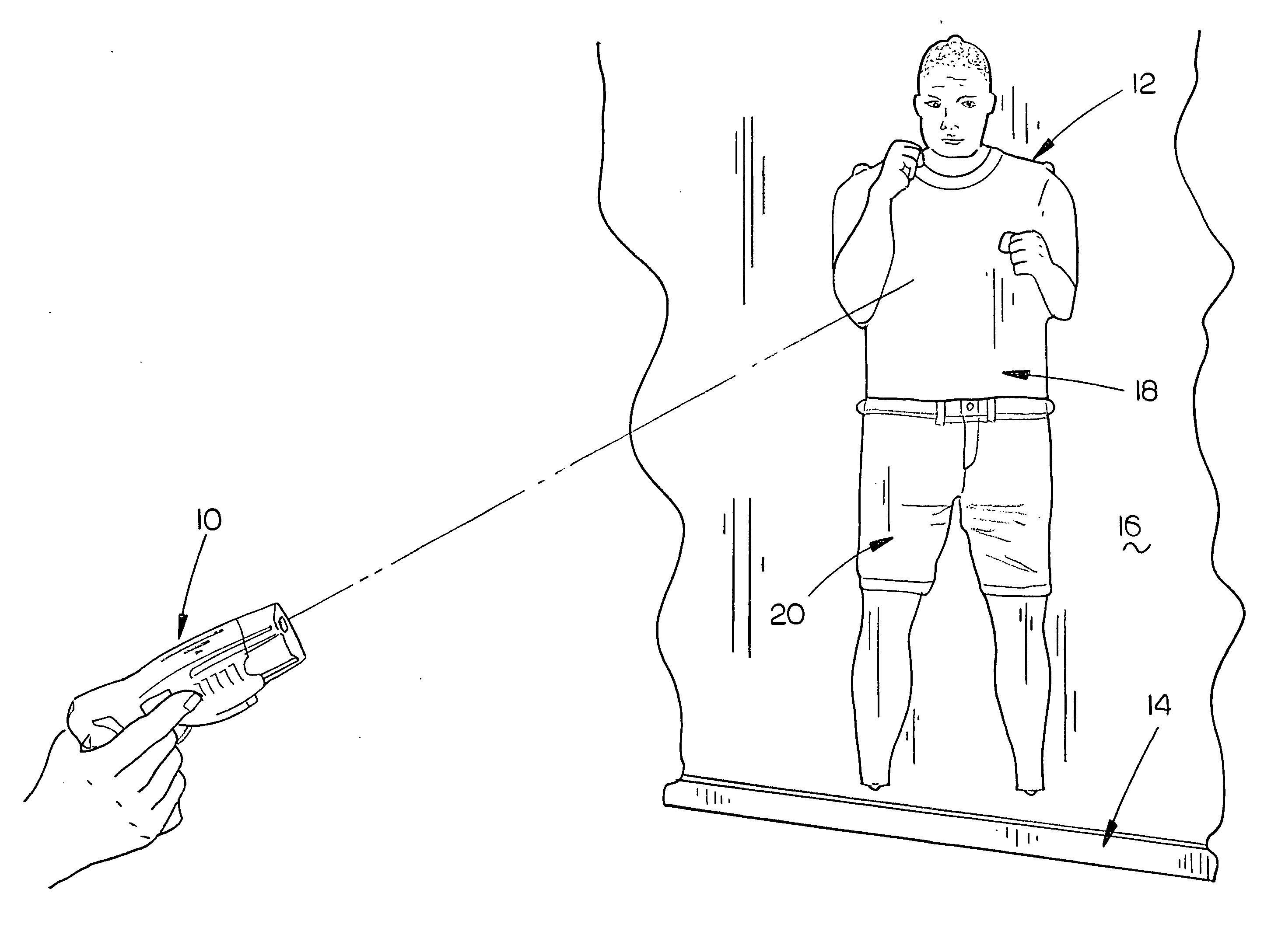
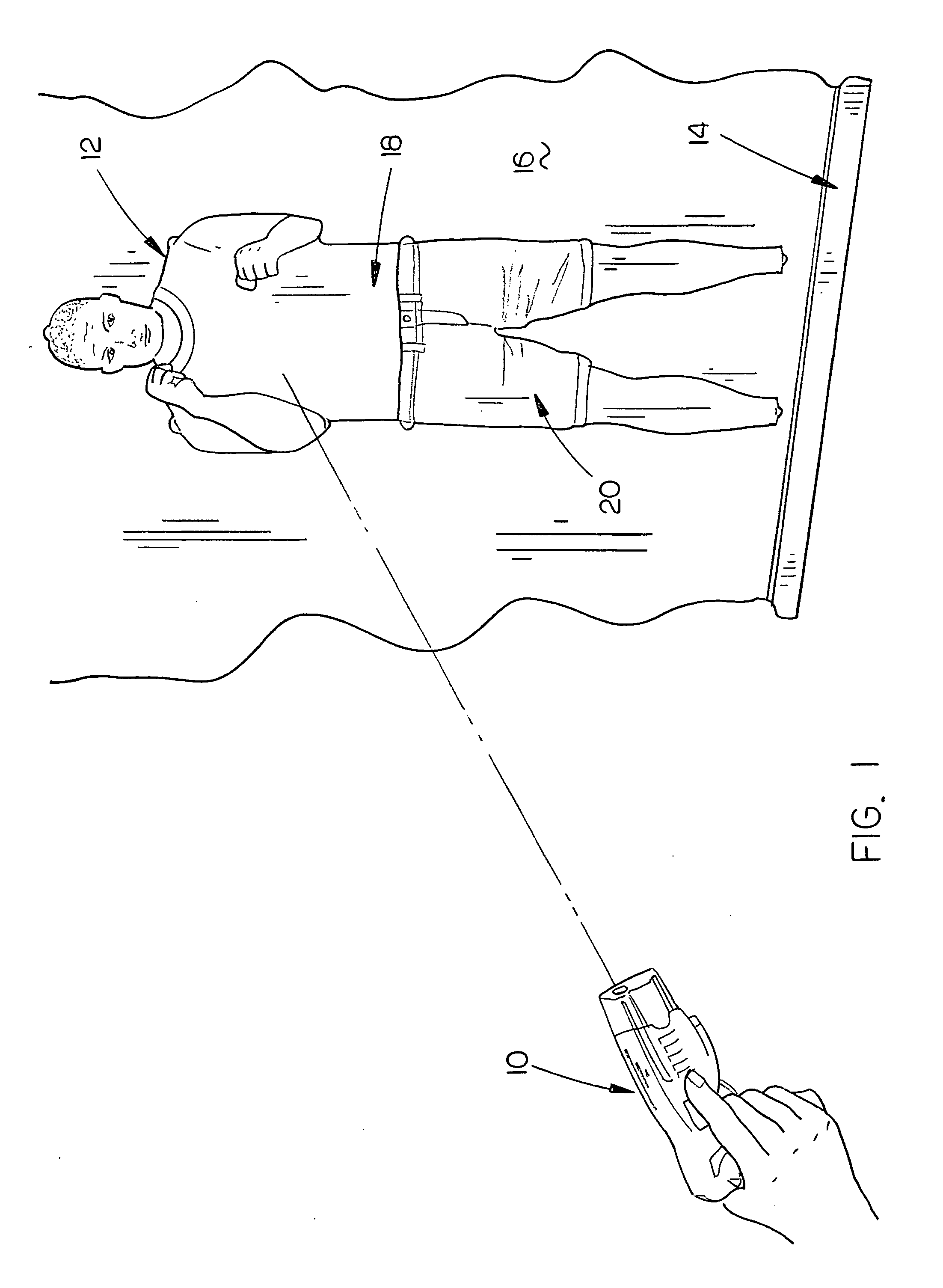
[0024]FIG. 1 illustrates an electronically controlled device or weapon 10 such as a Taser® gun shooting a round or one or more tethered darts into the target 12 of this invention. Normally the target 12 will be mounted on some sort of support or stand 14 having a supporting surface 16 thereon. The target 12 may be pinned, tacked or otherwise selectively removably secured to the sup...


PUM


Abstract

A training target is described for electronically controlled devices or weapons such as a Taser® gun. The target includes a front sheet having an electrically conductive sheet positioned at the back side thereof with the target being in the shape of a substantially life-size human being. The image of the human being is printed on the front face of the front sheet. The sheets may be reversed so that the image is printed on the electronically conductive sheet.

Description

BACKGROUND OF THE INVENTION[0001]1. Field of the Invention[0002]This invention relates to a practice target for a Taser® type gun or weapon and more particularly to a practice target which is in the shape of a human figure or being. Even more particularly, this invention relates to a practice target comprising a front sheet, having front and rear sides, with an electrically conductive sheet mounted on the back side thereof.[0003]2. Description of the Related Art[0004]Weapons that deliver electrified projectiles are used for self defense in law enforcement. A weapon that is extremely well known is the Taser® gun which fires two projectiles or darts from a hand-held device to deliver a stimulus signal to a person or animal. The projectiles remain tethered to a power supply in the hand-held device by a pair of insulated wires. In some cases, more than two darts may be fired from the weapon.[0005]Prior to this invention, there were no effective targets which were available for training ...

Claims


Application Information

Patent Timeline
Patent Type & Authority Applications(United States)
IPC IPC(8): F41G3/26A63F9/24
CPCF41J5/044F41J5/04
Inventor ODORISIO, TIM
Owner ODORISIO TIM
Why Eureka
Try Eureka