
Set of cyclic swashplates for controlling the pitch of blades of a main rotor, and a rotor provided with such a set

a technology of cyclic swashplates and blades, which is applied in the direction of propulsive elements, propellers, vessel construction, etc., can solve the problems of scissors links occupying a large amount of space, first, second, and third hinges subjected to high levels of wear, and require expensive and repeated maintenance actions

Active Publication Date: 2011-04-28
EUROCOPTER
View PDF5 Cites 8 Cited by
  • Summary
  • Abstract
  • Description
  • Claims
  • Application Information

AI Technical Summary

Benefits of technology

The present invention provides a set of cyclic swashplates for controlling the pitch of blades of a main rotor of a rotorcraft that are inexpensive and robust. The set includes a non-rotary swashplate retained against rotation about the axis of rotation and a rotary swashplate suitable for rotating about the axis of rotation. The set also includes drive means connecting the rotary swashplate and the rotor mast in rotation about the axis of rotation. The invention provides a single drive arm that is connected to the rotor mast and the rotary swashplate, which is robust and well-proven. The invention also includes a slideway connection means and an annular linear connection means that securely connect the drive arm to the rotor mast and the rotary swashplate, respectively. The non-rotary swashplate has fluting secured to it, which allows for smooth operation. The invention also provides a rotorcraft rotor with the set of cyclic swashplates and the drive means.

Problems solved by technology

Although effective, it is found that the first, second, and third hinges are subjected to high levels of wear requiring expensive and repeated maintenance actions.
To remedy that, scissors links are often overdimensioned, and thus end up being heavy and expensive to fabricate.
In addition, scissors links occupy a large amount of space, given the movements they must be free to make.
Nevertheless, the space occupied by that solution continues to be considerable.
In addition, there is a risk of frost forming on the rigid drive tracks and that can disturb the operation of the point connection means.

Method used


Image

  • Set of cyclic swashplates for controlling the pitch of blades of a main rotor, and a rotor provided with such a set
  • Set of cyclic swashplates for controlling the pitch of blades of a main rotor, and a rotor provided with such a set
  • Set of cyclic swashplates for controlling the pitch of blades of a main rotor, and a rotor provided with such a set

Examples


Embodiment Construction

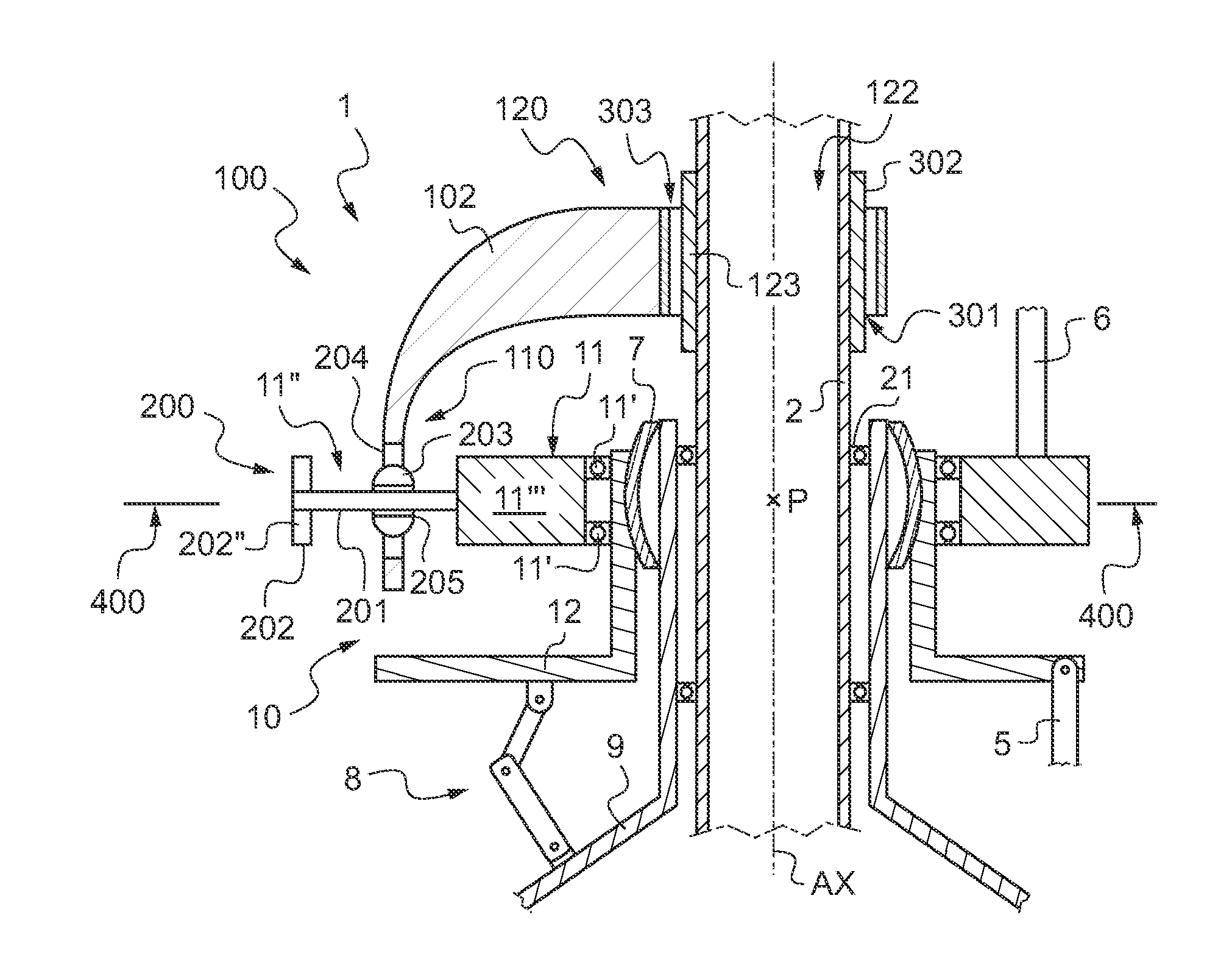
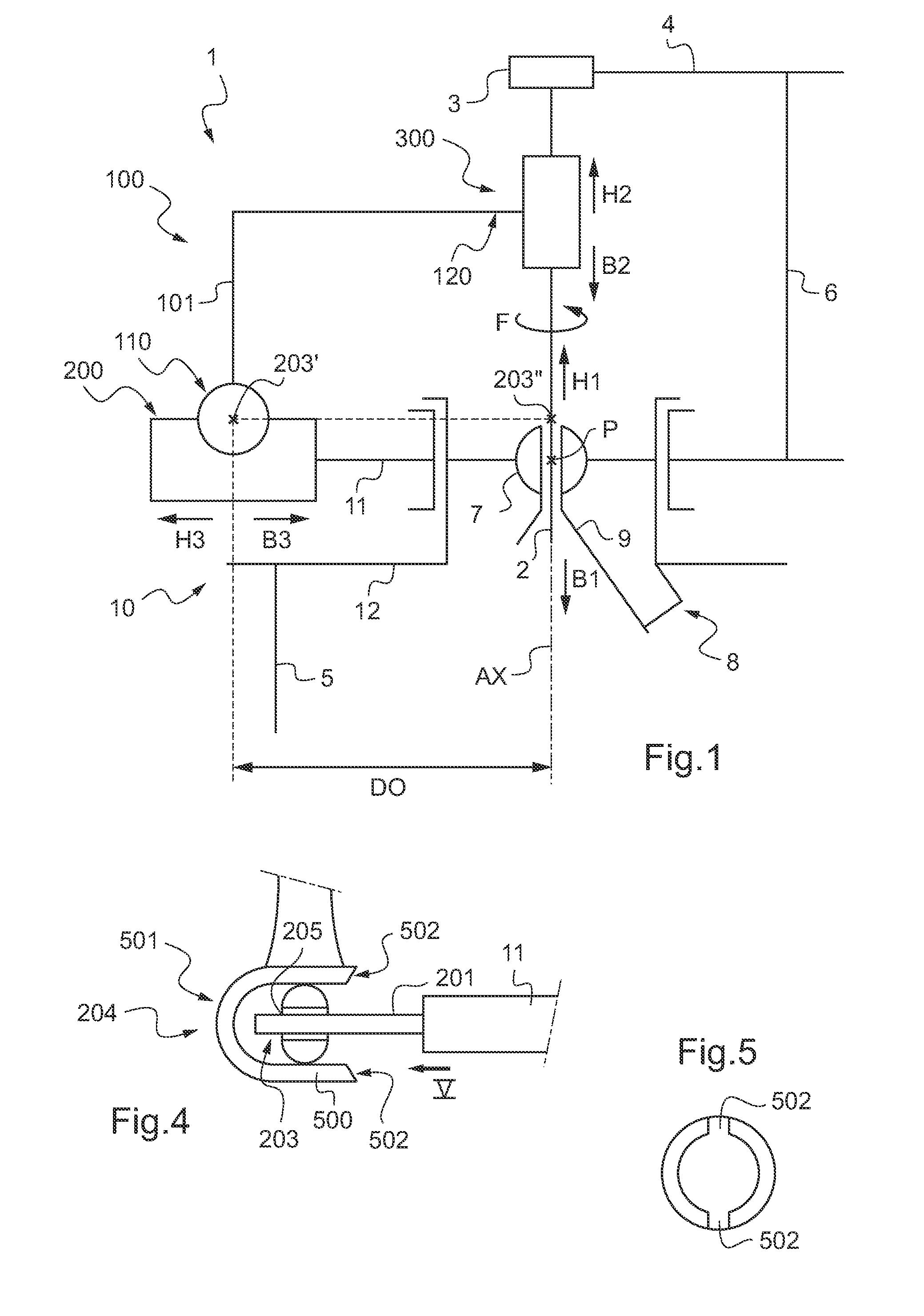
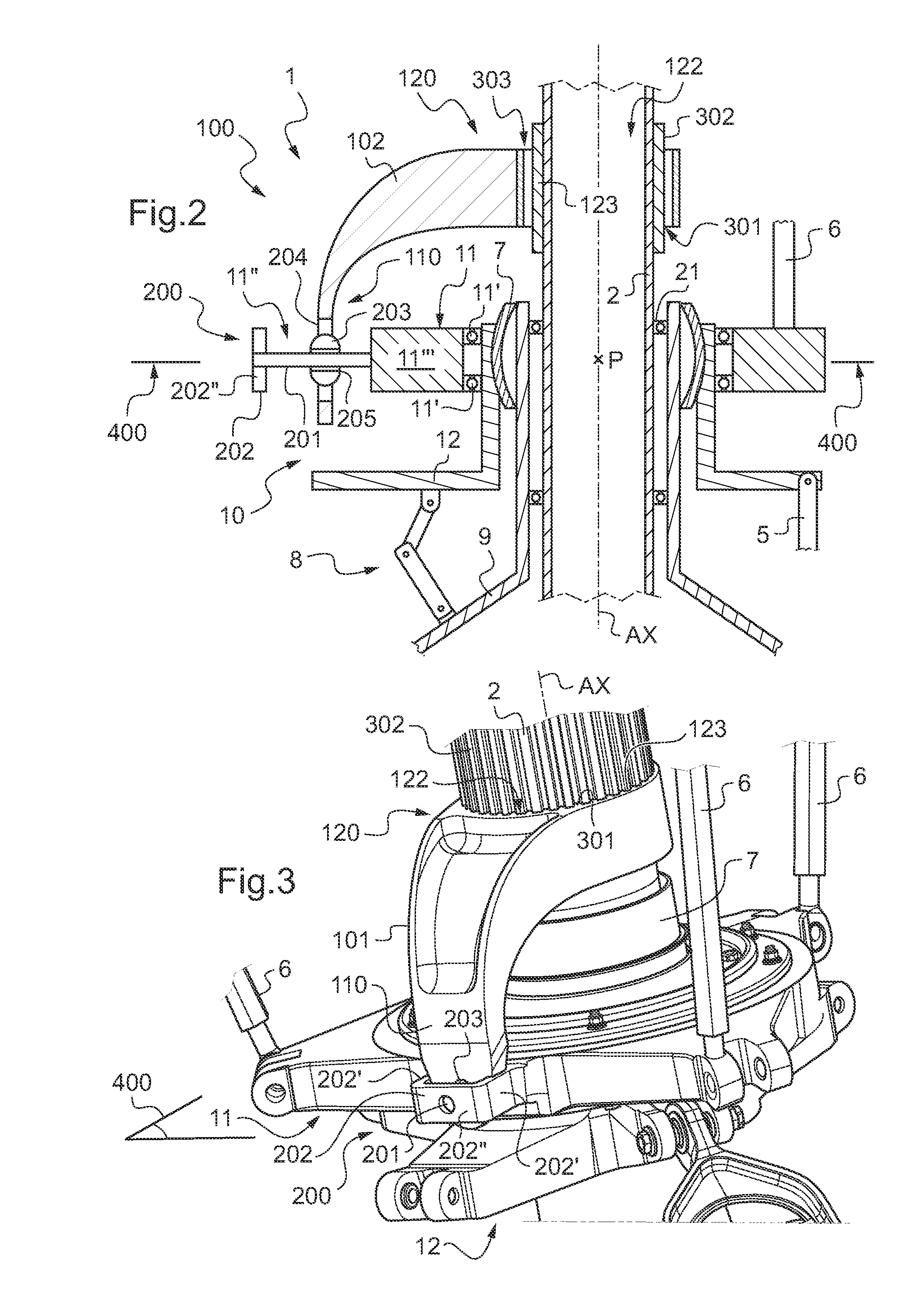
[0054]FIG. 1 depicts a rotor 1 provided with a rotor mast 2 for driving a plurality of blades 4 in rotation about an axis of rotation AX, each blade 4 being fastened to the rotor mast 2 by a common hub 3.

[0055]Since the rotor 1 is a main lift and propulsion rotor of a rotorcraft, it is provided with a set 10 of swashplates connected to the flight controls by servo-controls 5.

[0056]More precisely, the swashplate assembly 10 comprises a non-rotating plate 12 arranged on a ball joint 7 of the mast 2 that is mounted to slide on an element 9 of the rotorcraft. In addition, the non-rotary swashplate 12 is connected to the element 9 by a non-rotary scissors link which retains the non-rotary swashplate against any rotation about the axis of rotation AX.

[0057]Other means for retaining the non-rotary swashplate relative to the element 9 can be envisaged without going beyond the ambit of the invention. For example, it is possible to implement the retaining means described in document FR 2 768 ...


PUM


Abstract

A set (10) of cyclic swashplates (11, 12) for controlling the pitch of blades (4) of a main rotor (1) of a rotorcraft. The set includes a non-rotary swashplate (12) retained against rotation about an axis of rotation (AX) and a rotary swashplate (11) suitable for rotating about the axis of rotation (AX). The set (10) also includes drive means (100) with a drive arm (101) and an annular linear connection means (200) secured to the rotary swashplate (11). A first end (110) of the drive arm (101) is connected to the rotary swashplate (11) by the annular linear connection means (200). A second end (120) of the drive arm (101) is connected to a rotor mast (2) by slideway connection means (300) of the drive means (100).

Description

CROSS REFERENCE TO RELATED APPLICATION[0001]This application claims the benefit of application no. FR 09 05111 filed Oct. 23, 2009, the disclosure of which is incorporated herein by reference.FIELD OF THE INVENTION[0002]The present invention relates to a set of cyclic swashplates for controlling the pitch of blades of a main rotor, and to a rotor provided with such a set.BACKGROUND OF THE INVENTION[0003]The main rotor of a rotorcraft serves to provide rotorcraft with lift, and indeed with propulsion. Conventionally, such a main rotor driven by an appropriate power plant comprises a rotor mast that sets a plurality of blades into rotation by means of a rotor hub.[0004]In order to control the movement of the rotorcraft, the pitch of the blades of the main rotor is controlled, i.e. their angle of aerodynamic incidence is controlled. Under such circumstances, the blade pitch is adjustable by means of pitch control rods and a set of cyclic swashplates surrounding the rotor mast, the cycl...

Claims


Application Information

Patent Timeline
Patent Type & Authority Applications(United States)
IPC IPC(8): B64C27/605
CPCB64C27/605
Inventor GIRARD, VINCENT
Owner EUROCOPTER
Learn More