Respiration valve

a technology of valve and wall segment, applied in the field of valve, can solve the problems of mechanically operated valves being sensitive to wear and fatigue, clumsy valves, heavy, etc., and achieve the effect of pressure needed to pinch the wall segment, excellent elastic properties, and high tensile strength

Active Publication Date: 2012-08-14
IPR HLDG APS
View PDF19 Cites 4 Cited by
  • Summary
  • Abstract
  • Description
  • Claims
  • Application Information

AI Technical Summary

Benefits of technology

[0012]The invention furthermore concerns a respiration valve according to the above, wherein the pneumatic pinch valve comprises a channel with a flexible wall in which channel the material flows. The channel is molded as an integrated part of a surrounding chamber and the valve functionality is obtained by pinching the flexible wall based on pressure from fluid, such as air, introduced into the chamber. The flexible wall of the channel is characterized by comprising two opposing angularly interconnected wall segments being angularly connected at interconnection points, where these two wall segments are pinched towards each other based on pressure from the fluid. The pneumatic pinch valve according to the invention presents a geometrically very simple design made out of only very few parts and no mechanically moving parts. It can thus be made very small and compact and at the same time very robust and inexpensive. Because of the small size, it can also be made very light. Furthermore, the air or fluid pressure needed to operate the valve is very low because of the flexibility and shape of the channel and because the volume of the pressure chamber can be made small. Because the wall segments are angularly connected at interconnection points, the shape of the flexible channel is well defined and controllable not only in the fully opened and closed positions but also at all positions in-between. This thus makes the pinch valve according to the invention extremely suitable also for the continuous regulation of a flow and not only for shutting it off or opening it. Also, the valve design contains the important quality of closing the channel completely, even if dust or dirt particles are present in the material flow. Compared to prior art, the present valve is further advantageous by not having weak and seriously stressed regions because the closing shape is already built into the design by the angular connection of the wall segments. In other words, the pinch valve is not as prone to fatigue and wear and has a long life expectancy. Yet a further advantage of the present invention is the absence of any parts protruding into the flow channel which together with the smooth inner surfaces in the channel keep the flow resistance in the channel low. By choosing the distance between the interconnection points in the valve in accordance with the geometry and size of the channel before and after the valve, one can even obtain that the flow resistance is not affected by the presence of the valve in its open configuration. The above mentioned properties also facilitate the cleaning and rinsing of the channel.
[0013]In another embodiment of the invention the wall segments of the pinch valve in a respiration valve are angularly connected with an acute angle between the wall segments.
[0014]In a further embodiment of the invention the channel in a pinch valve in a respiration valve as described above has a cross sectional elongated shape, whereby the distance between the interconnection points is larger than the distance between the two opposing wall segments. This shape is advantageous in that the pressure needed to pinch the wall segments together to a closed position is lower as the wall segments are close to each other.
[0015]Another embodiment of the invention concerns a respiration valve comprising a pinch valve according to the above wherein the cross sectional elongated shape approximately corresponds to a hexagon.
[0016]In a preferred embodiment the flexible wall of the pinch valve is made from silicone rubber (elastomer). This specific choice of material is advantageous as it is a light material which has excellent elastic properties, high tensile strength and does not exhibit hysteresis, meaning that it has good closing and reopening properties. It also has a high resistance to chemicals and is thermally stable and unaffected by environmental extremes. It also has good medical and sanitary properties including physiological inertness and high tolerance to humidity. Furthermore, the pinch valve can be moulded in only one single or a very few parts using the silicone.
[0017]Another embodiment of the invention concerns a respiration valve comprising a pinch valve according to the above wherein the pneumatic pinch valve is made as a hybrid comprising a flexible wall made of silicone rubber and a chamber made of a plastic. Hereby is obtained a reduction of the wall thicknesses in areas and thus a corresponding reduction of the overall weight of the respiration valve.

Problems solved by technology

However, all of these types of valves in a respiration valve yield several problems and disadvantages.
Secondly, any metal parts make the valve far more clumsy, heavy, and take up a considerable amount of space.
Furthermore, a mechanically operated valve is sensitive to wear and fatigue during many opening and closing operations.
However, such a cylinder will inevitably form foldings and wrinkle when pressed together.
A valve like this will not be able to close tightly unless the pressure in the surrounding fluid is relatively high, and furthermore, as the shape and the area of the opening are uncontrollable, the valve will be unsuitable for regulation purposes.
This means that the cylinder is subjected to a substantial and somewhat permanent deformation giving the cylinder wall a crease at the desired positions.
Nevertheless, some big problems still remain.
First, although the wrinkling is avoided, a valve as described above still cannot close completely in the corners at the ends of the constriction seam due to the shape of the cylinder unless the pressure in the surrounding fluid is relatively high.
Second, the steps taken to ensure that the tube is pinched together along a linear seam instead of the uncontrollable folding have inevitably damaged the tube to some extent, thereby reducing the lifetime of the valve and also reducing the resistance to wear and fatigue considerably.
The guiding vanes inside the membrane, however, lead to more parts in the valve which complicates the structure and the manufacturing hereof, also because the guiding vanes are of a rather complicated geometrical shape.
This valve is therefore more expensive to produce and cannot be made as compact or small, the larger dimensions again also leading to the need for a higher air pressure to close the valve.
Furthermore, the guiding vanes inside the tube are undesirable in many applications as they increase the flow resistance considerably.
During such a snap-through the open flow area changes very fast and suddenly leading to difficulties in adjusting and regulating the flow.
The valve is thus not so adequate for regulation purposes.
The construction of the valves themselves yields a heavy and clumsy design leading to a quite heavy and big apparatus which is inappropriate in the testing situation of patient, both for a patient at rest, but even more so for measurements made on a patient during different physical tests.
A further disadvantage is the mechanical moving parts which although they are not in direct contact with the breathing of the patient remain a hygienic problem.
Also, the design of the respiration valve with the placing of the pinching valves is disadvantageous as the dead space between the two valves is considerable rendering the measurements correspondingly inaccurate.

Method used


Image

  • Respiration valve
  • Respiration valve
  • Respiration valve

Examples


Embodiment Construction

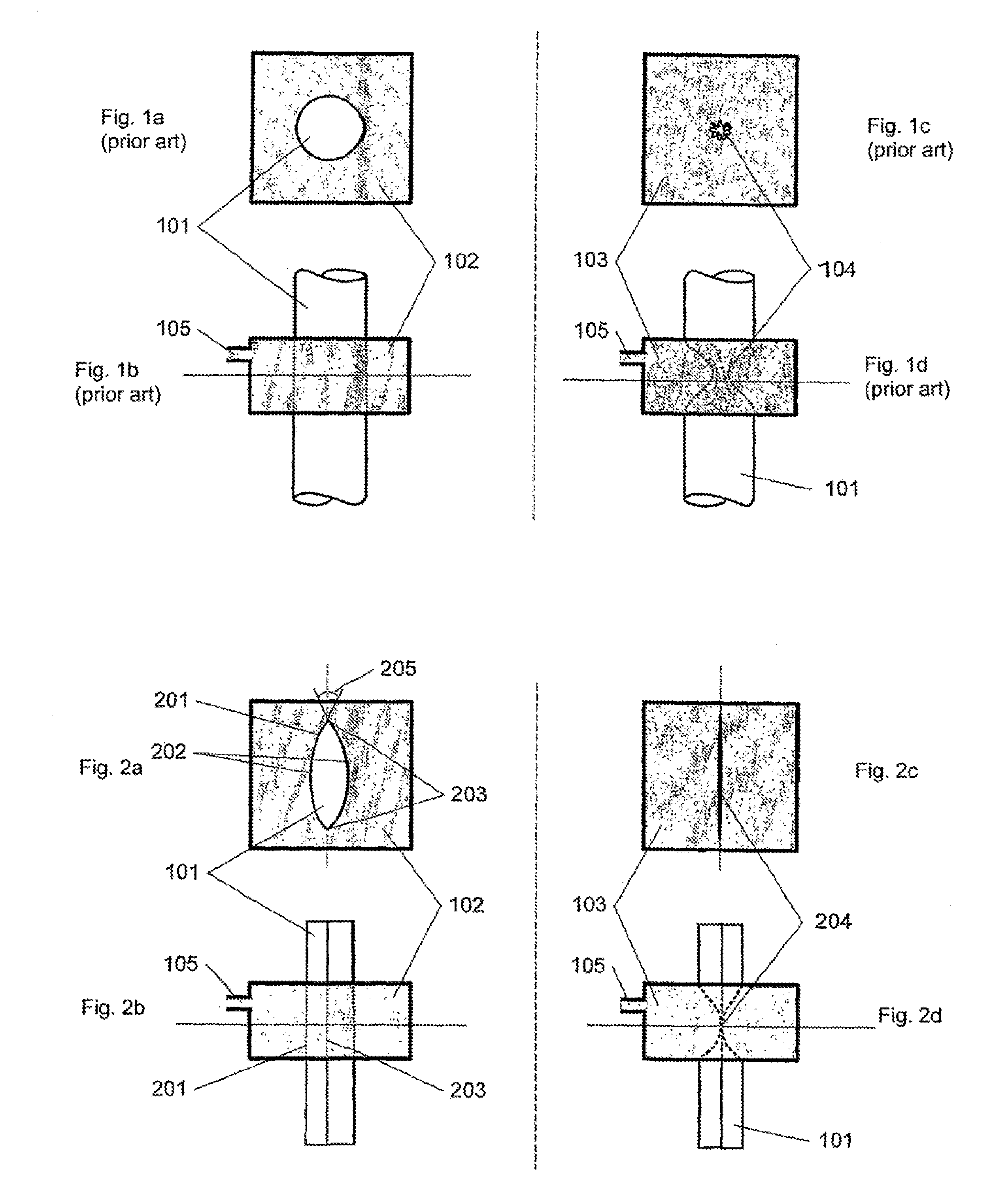
[0025]FIGS. 1a-1d illustrate the principle of a pneumatic pinch valve as known in the art. FIGS. 1a-1b illustrate top and side views of the open configuration of the valve, while FIGS. 1c-1d illustrate top and side view of the closed configuration. A cylindrical channel or tube 101 is surrounded by a chamber 102 with an injection port 105, and in close connection to the channel 101. When the chamber 102 is filled with air or some fluid under pressure 103 the cylindrical channel 101 will be pinched as shown schematically in FIGS. 1c-1d and the valve is closed. However, if the channel 101 is a conventional more or less circular tube, the valve will have difficulties in closing completely as the tube will wrinkle in compression 104 in some undefined shape not known a priori. Furthermore, this wrinkling 104 leads to severe wear and fatigue of the channel material even after a relatively few closing and opening operations of the valve.

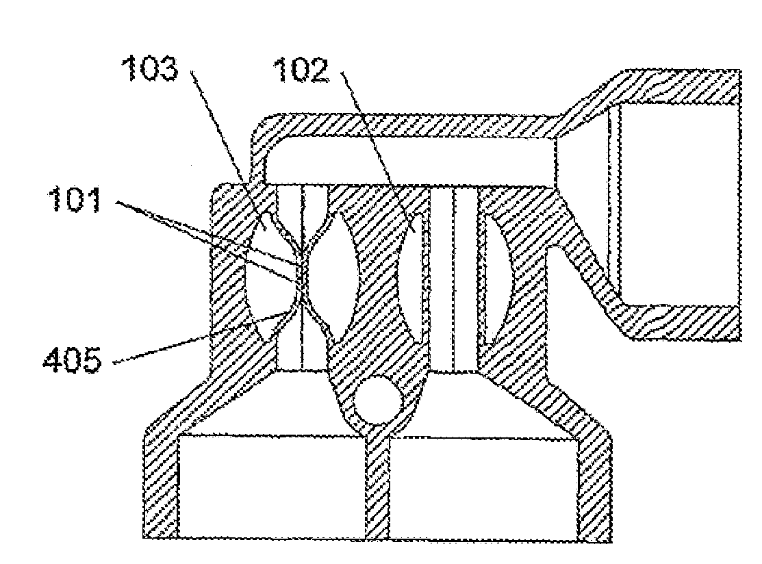
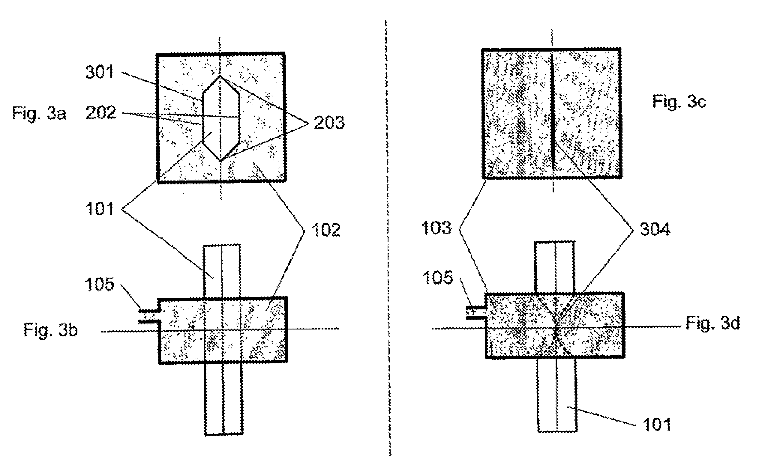
[0026]FIGS. 2a-2d illustrate a pinch valve as used in...


PUM


Abstract

The present invention relates to a respiration valve (401) for performing respiration tests on e.g. humans, consisting of at least three ports, a first mouth port (402) and two breathing ports (403, 404). The breathing ports (403, 404) comprise pneumatic pinch valves consisting of a channel (101) with a flexible wall (201) to be used for the flow of material and molded as an integrated part of a surrounding chamber (102). The flexible wall (201) comprises two opposing angularly interconnected wall segments (202) which are angularly connected at interconnection points (203) and which flexible wall (201) is pinched by a pressure from fluid, such as air, introduced into the chamber (102). The cross sectional shape corresponds in one embodiment approximately to a elongated hexagon. The construction of the respiration valve (401) comprising these pneumatic pinch is valves enables a very small, light, hygienic, and safe yet inexpensive construction with a long life expectancy. The respiration valve (401) is preferably completely or partially made of silicone rubber.

Description

[0001]The present invention relates to a respiration valve for performing respiration tests on e.g. humans, where the respiration valve comprises pinch valves.BACKGROUND OF THE INVENTION[0002]One way of measuring and examining the well-functioning and performance of a patient's heart is by determining the cardiac output. A well-established method or principle to measure the cardiac output is by inert gas rebreathing, which is a non-invasive measurement method. This principle utilizes a closed rebreathing system where a small amount of a blood soluble, physiologically inert gas is inhaled from a rebreathing bag. Among other things, a concentration curve of the inert gas can be extracted from the measurements during rebreathing and the wash-out rate, which is proportional to the cardiac output, can be calculated. During the measuring, the patient is breathing through a respiration valve which allows switching from breathing air to rebreathing the inert gas mixture from the bag and swi...

Claims


Application Information

Patent Timeline
Patent Type & Authority Patents(United States)
IPC IPC(8): A61M16/00A61M16/20
CPCA61M16/08A61M16/20A61M16/0833A61M16/208A61M16/202
Inventor CLEMENSEN, PETER CHRISTIANJORGENSEN, KLAS
Owner IPR HLDG APS
Why Eureka
Try Eureka