Conveyor belt assembly

a conveyor belt and assembly technology, applied in the field of conveyor belts, can solve the problems of increasing potential, impeding the rapid removal of water from conveyor belt assemblies, and not without problems, and achieve the effect of reducing the dispersion of fluid jets

Inactive Publication Date: 2005-02-15
JOHN BEAN TECH CORP
View PDF15 Cites 36 Cited by
  • Summary
  • Abstract
  • Description
  • Claims
  • Application Information

AI Technical Summary

Benefits of technology

In accordance with certain embodiments of the present invention, a conveyor belt assembly for conveying an object to be portioned by a fluid jet is provided. The conveyor belt assembly includes a conveyor belt formed from at least a first and a second picket each having a length comprised of a sequence of geometrically shaped links disposed transversely across the conveyor belt. The pickets include upper edge portions that form a conveying surface for supporting and advancing the object to be portioned. The upper edge portions are tapered in the upward direction to reduce dispersion of the fluid jet during impingement of the fluid jet on the conveying surface.

Problems solved by technology

Although existing conveyor belt assemblies of a lattice type design are capable of conveying products for use in portioning machines utilizing fluid jets, they are not without problems.
First, the conveyor belt assemblies have impediments to rapid water removal—such as valleys, horizontal surface areas, or other configurations that impede rapid cutting-fluid removal.
Therefore, cutting fluid can accumulate on the conveyor surface, thereby increasing the potential that the position of the product on the conveying surface will be disrupted by floating the product or its position disrupted by direct impact of ricocheted (splashed back) cutting fluid from the fluid jet.
Further, these impediments to rapid cutting-fluid removal also subject the object to be portioned to increased fluid absorption, and also increase the amount of splash of the cutting fluid upon impingement of the conveyor belt assembly.
The impact of the splash can also cause shifting of the belt and the objects to be portioned, resulting in less precise cutting or portioning than desired.
Further yet, these impediments subject the conveying surface to increased rates of wear, since the fluid jet more directly impinges upon their surfaces.
Further, existing conveying systems lack a top surface that provides a sufficient gripping surface to hold and maintain the position of objects to be portioned.
Still further yet, the impediments cause the fluid jet to be disrupted as it attempts to pass through the conveyor surface.
This disruption of the fluid jet disrupts the collection of the spent cutting fluid as the fluid jet is dispersed in a wide range of directions, impeding its flow directly into the spent cutting-fluid collection means.
Further still, existing lattice type conveyor belts are prone to having varying distances between adjacent lattices as measured along the length of the belt.
Therefore, a belt that has inconsistencies in distances between adjacent lattices can decrease the accuracy of the portioning.

Method used


Image

  • Conveyor belt assembly
  • Conveyor belt assembly
  • Conveyor belt assembly

Examples


Embodiment Construction

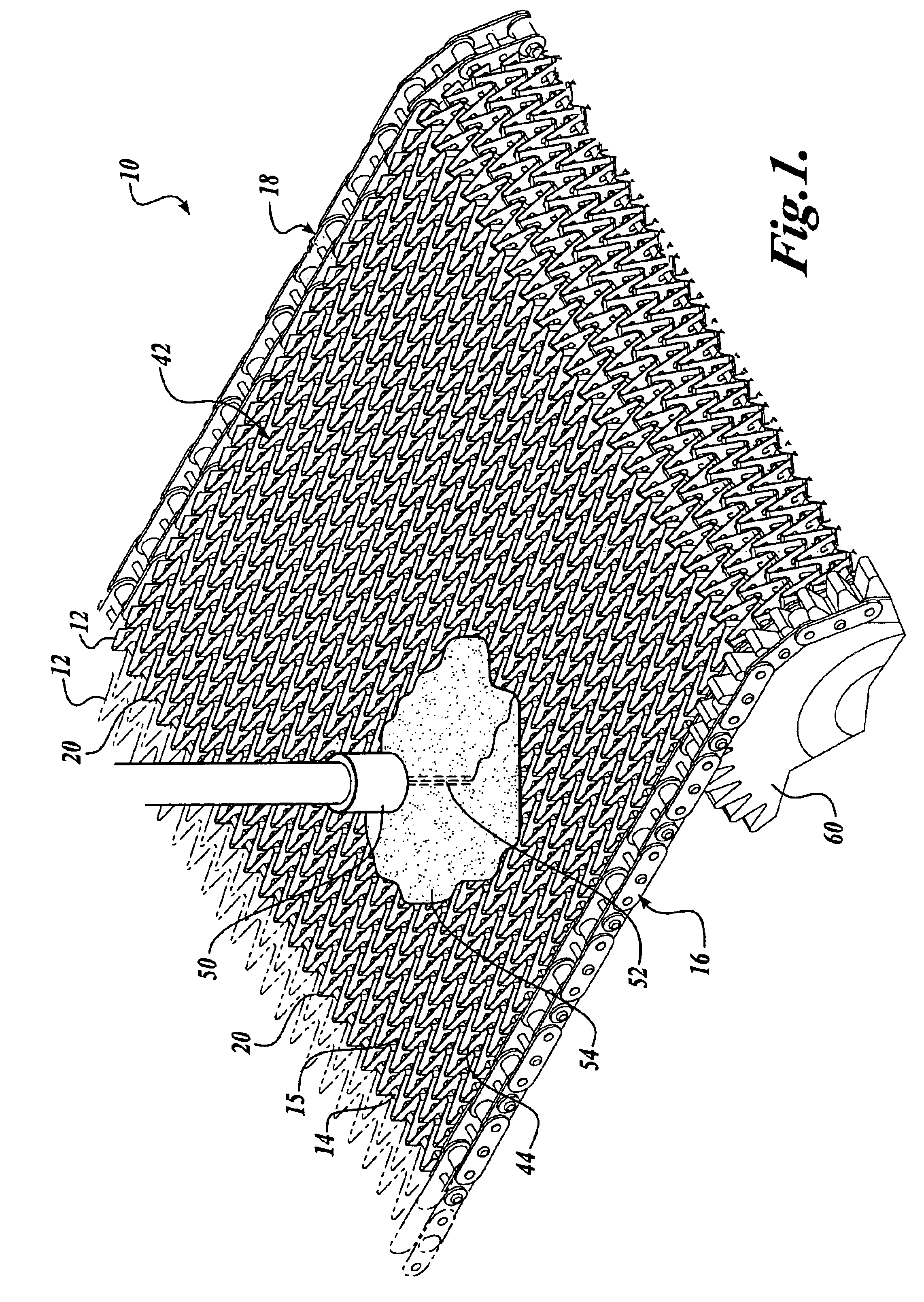
The present invention relates to a new design for a conveyor belt assembly that is particularly suitable for supporting objects to portioned, and more particularly for supporting objects to be portioned during fluid jet cutting operations. It should be noted that for purposes of this description, terminology such as left, right, vertical, horizontal, etc., are descriptive in nature and should not be construed as limiting.

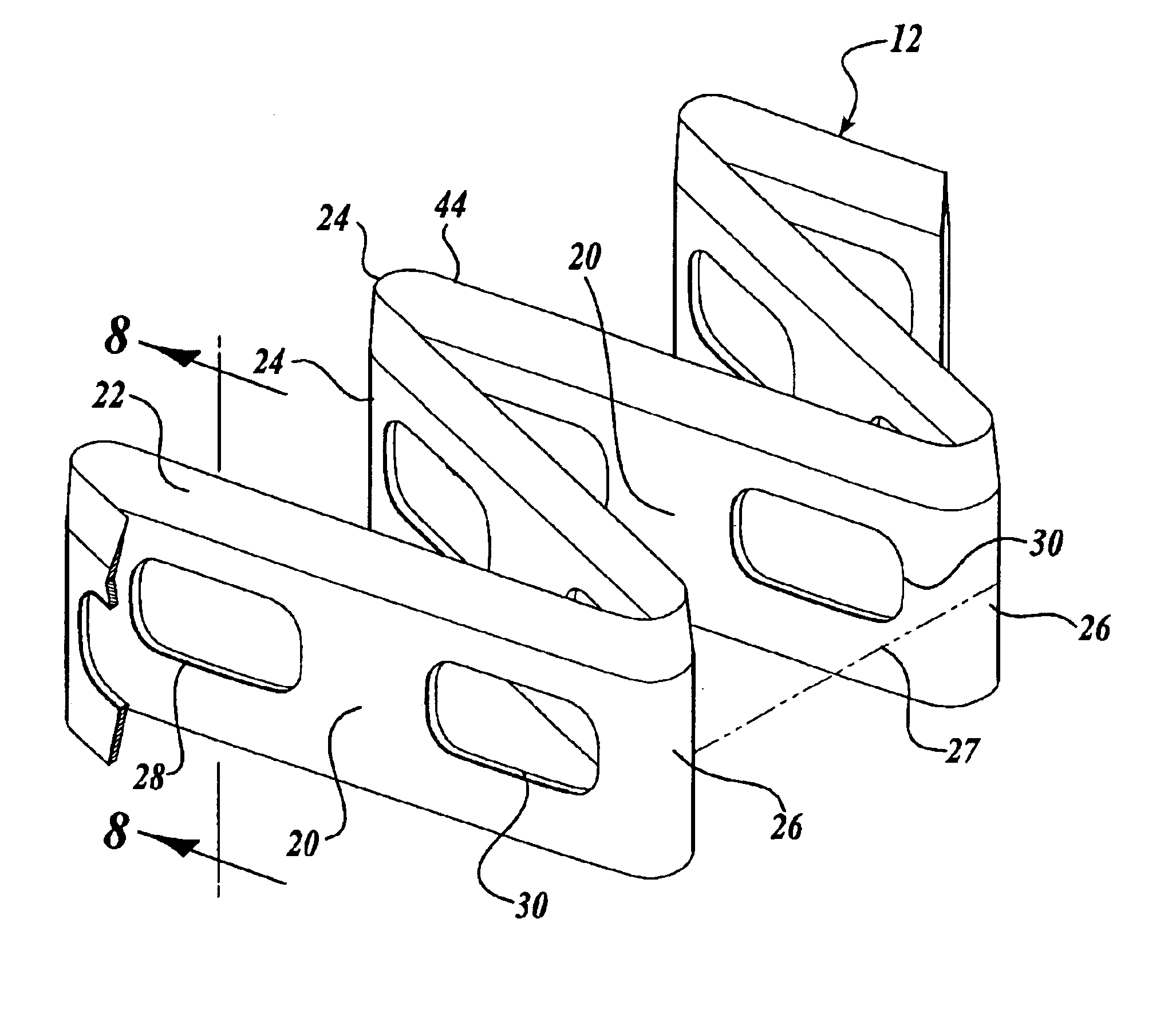
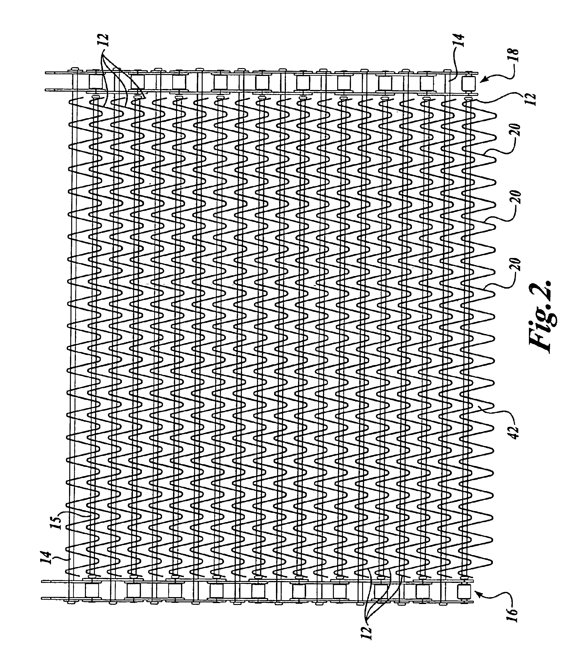
Referring to FIGS. 1 and 2, the conveyor belt assembly 10 is comprised of a conveying surface 42 formed from a plurality of pickets 12. The pickets 12 are pivotally joined to one another and to a left and right drive chain 16 and 18 by a plurality of connecting rods 14 and 15.

Referring specifically to FIG. 2, the connecting rods 14 and 15 are elongate shafts that extend transversely and horizontally just below the conveying surface 42. The connecting rods 14 and 15 are inserted through the pickets 12, pivotally joining adjacent pickets 12 to one another, and pivotal...


PUM

PropertyMeasurementUnit
interior anglesaaaaaaaaaa

Abstract

A conveyor belt assembly (10) for conveying an object to be portioned (54) by a fluid jet (52) is disclosed. The conveyor belt assembly (10) includes a conveyor belt formed from at least a first and a second picket (12) each having a length comprised of a sequence of geometrically shaped links (20) disposed transversely across the conveyor belt. The pickets (12) are disposed in a nested relationship to each other. The pickets (12) include upper edge portions (22) that form a conveying surface (42) for supporting and advancing the object to be portioned (54). The upper edge portions (22) are tapered in the upward direction to reduce dispersion of the fluid jet (52) during impingement of the fluid jet (52) on the conveying surface (42).

Description

FIELD OF THE INVENTIONThe present invention relates generally to conveyor belts, and more particularly, to conveyor belts for conveying objects to be portioned by high-speed fluid jets.BACKGROUND OF THE INVENTIONManufacturing processes of most products generally include the portioning of a raw or intermediary material into a desired shape or weight. In the food industry in particular, portioning systems are routinely used to trim foodstuffs into uniform sizes—for example, for steaks to be served at restaurants, chicken fillets in frozen dinners, or in chicken burgers. Also, excess fat, bone, and other foreign or undesired materials are routinely trimmed from foodstuffs. Much of the portioning / trimming of materials, in particular food products, is now carried out with the use of high-speed portioning machines utilizing high-speed fluid jets to portion objects conveyed upon a conveyor belt assembly.High-speed fluid jets impinge the product with a thin, high-velocity stream of water or...

Claims


Application Information

Patent Timeline
Patent Type & Authority Patents(United States)
IPC IPC(8): B26D7/20B26D7/00B26F3/00
CPCB26D7/20B65G17/064B26F3/004Y10T83/364Y10T83/0591Y10T83/2192
Inventor RUDY, NORMAN A.WILSON, DANIEL F.
Owner JOHN BEAN TECH CORP
Why Eureka
Try Eureka