Method, device, and system for controlling encircled flux

a technology of encircled flux and flux, applied in the direction of optics, lighting and heating apparatus, instruments, etc., can solve the problems of optical fiber overfilling, link loss measurement that is too high, reading may be overestimated, loss value that does not correspond to reality, etc., to achieve low operator skill, easy to use, and low cost.

Inactive Publication Date: 2011-04-28
LEVIN PIOTR ANATOLIJ +1
View PDF0 Cites 5 Cited by
  • Summary
  • Abstract
  • Description
  • Claims
  • Application Information

AI Technical Summary

Benefits of technology

[0021]Therefore, it is an aspect of the invention to provide an inexpensive and robust alternative to current methods and devices for controlling EF.
[0022]It is a further aspect of the present invention to provide an alternative to current methods and devices for controlling EF that is easy to use, thus relying little on operator skill.
[0023]It is a further aspect of the present invention to provide a method and / or device for controlling EF that may be easily adapted to existing fiber optic testing equipment.

Problems solved by technology

If the launch condition is such that too many modes are excited, then the optical fiber will be overfilled and produce link loss measurements that are too high.
Thus the loss reading may be overestimated, leading to loss value that will not correspond to reality.
If the launch condition is such that too few modes are excited, then the optical fiber will be underfilled and produce link loss measurements that are too low.
This may produce misleading and overly optimistic results.
Controlling launch conditions, and thus EF, can be very challenging.
Although mandrel wrapping is able to achieve the desired results, this method has its disadvantages.
Determining the correct size of the mandrel and how many turns of the mandrel are appropriate can be challenging.
Specifically, the optical element in either of the embodiments mentioned above is very delicate.
It must be manufactured at significant expense to exacting standards.
Any manufacturing imperfection, including scratches, smudges, and thickness variability will render the optical element unusable for its purpose.
Moreover, given the precision with which the optical element must be applied to the optical system, even a perfectly manufactured optical element may easily be misaligned or otherwise positioned incorrectly to achieve the desired results.
However, this product is a jumper that is added to a light source and is not adapted to allow a light source to meet the ISO 14763-3 standard for EF directly from the light source without the use of external launch manipulation.

Method used


Image

  • Method, device, and system for controlling encircled flux
  • Method, device, and system for controlling encircled flux
  • Method, device, and system for controlling encircled flux

Examples


Embodiment Construction

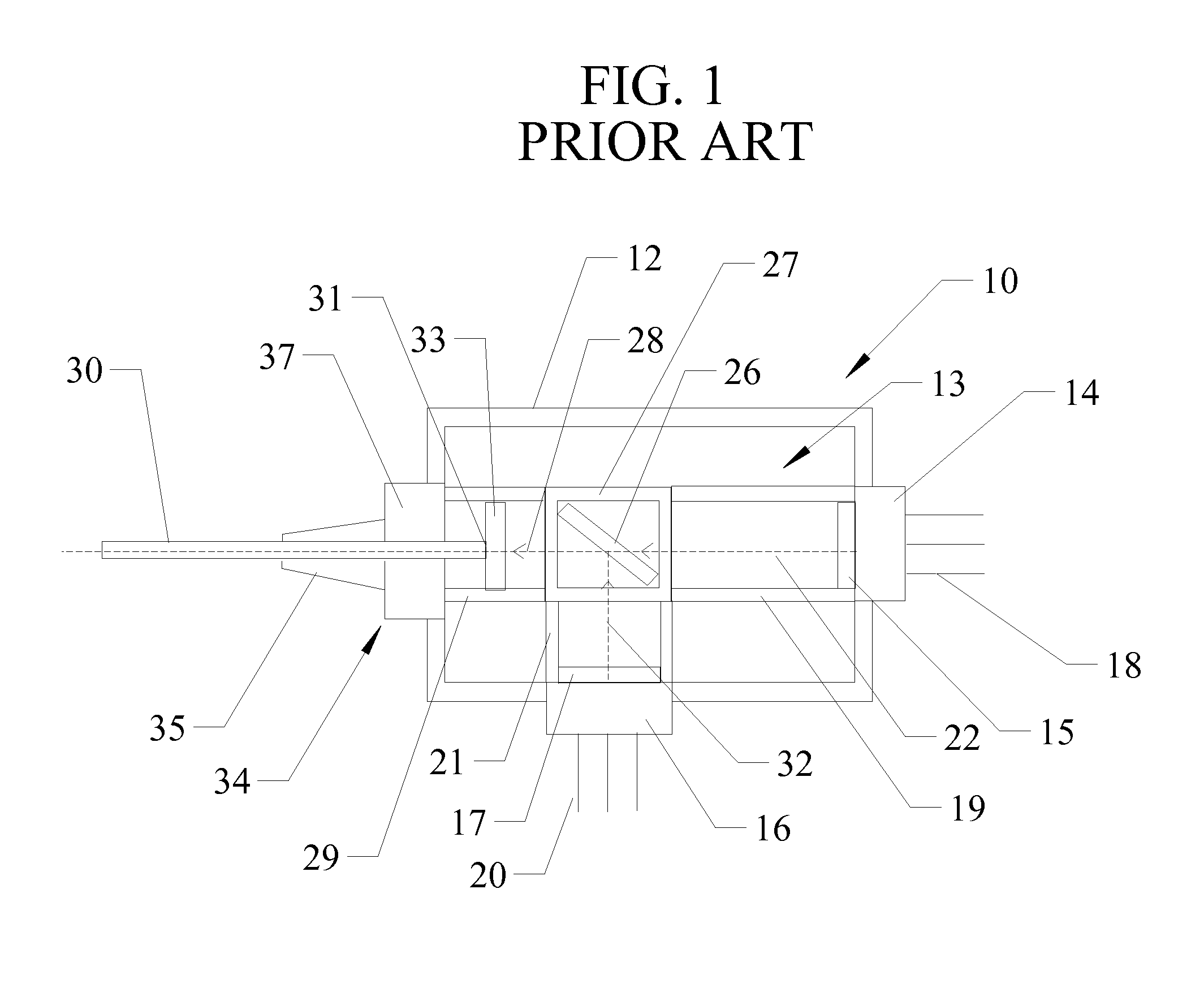
[0036]Referring first to FIG. 1, an illustration of a prior art light module 10 is shown. The light module 10 shown in FIG. 1 is a type commonly used within fiber optic test instruments. Examples of such light modules are the FOD 3105 Dual LED Module, the FOD 3206 Laser Diode Module, and the FOD 3226 Triple LD Module, manufactured by Fiber Optic Devices of Vilnius, Lithuania. These light modules may have single or multiple light sources and may produce light of any wavelength. Such a light module may be used within any portable or stationary fiber optic test instrument, such as the EXFO FLS-300 Light Source, the FOD 2114 Triple Laser Light Source, the AFL Telecommunications Noyes® OLS1-Dual LED Light Source with Wave ID, the EXFO IQS-2100 Light Source, and the EXFO FLS-2200 Broadband Source, that may test single or multi-mode optical fibers.

[0037]The light module 10 of FIG. 1 is a dual light emitting diode (LED) light module that includes a housing 12, two LEDs 14 and 16 from which ...


PUM


Abstract

A light module, a fiber optic connector, and a system that each include a screw in communication with an optical fiber that is movable such that the optical fiber may be deformed to a desired level in order to control encircled flux by extinguishing undesired modes of light launched through the optical fiber.

Description

CLAIM OF PRIORITY[0001]This application claims the benefit of priority of U.S. Provisional Patent Application Ser. No. 61 / 279,597, filed on Oct. 23, 2010.FIELD OF THE INVENTION[0002]The present invention relates to the transmission of optical signals through optical fibers, and in particular to methods, devices and systems for controlling the encircled flux of optical signals transmitted through optical fibers to achieve repeatable, consistent optical fiber testing.BACKGROUND OF THE INVENTION[0003]The present invention pertains to transmission of optical signals through optical fibers. Optical signals are transmitted by applying a light source to an optical fiber. The light source and the optical fiber must be appropriately aligned with one another in order to couple as much light as possible into the optical fiber. Light sources may be aligned to two different types of optical fibers, single-mode optical fibers and multi-mode optical fibers. Single-mode optical fibers can accommoda...

Claims


Application Information

Patent Timeline
Patent Type & Authority Applications(United States)
IPC IPC(8): G05D25/00G02B6/36
CPCG05D25/02G02B6/4246
Inventor LEVIN, PIOTR ANATOLIJGAVRILINAS, NIKOLAJUS
Owner LEVIN PIOTR ANATOLIJ
Why Eureka
Try Eureka