
Method and device for assisting a vehicle operator

a vehicle operator and vehicle technology, applied in the direction of vehicle position/course/altitude control, process and machine control, instruments, etc., can solve the problems of being disruptive to the vehicle operator, affecting the operation of the vehicle, and being difficult for the driver to determin

Inactive Publication Date: 2011-04-28
CONTINENTAL TEVES AG & CO OHG
View PDF14 Cites 42 Cited by
  • Summary
  • Abstract
  • Description
  • Claims
  • Application Information

AI Technical Summary

Benefits of technology

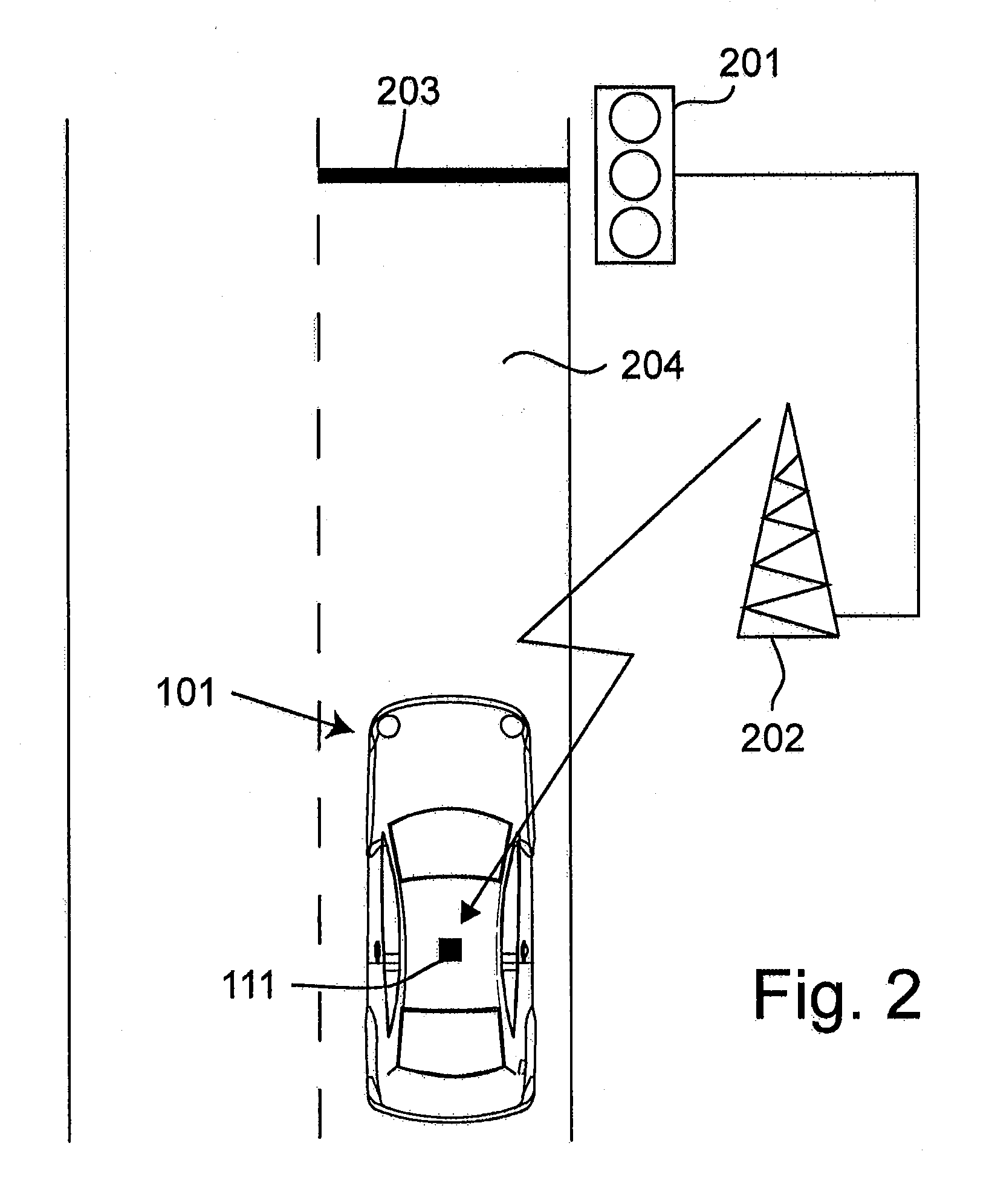
[0008]An advantage of the invention is that it is possible to avoid a vehicle operator unintentionally crossing the stop line while the set of traffic lights is in the second operating state in which it is not permitted to cross the stop line. As a result, road safety at sets of traffic lights is increased. A further advantage of the invention is that the longitudinal speed of the vehicle can be influenced directly or indirectly via a corresponding recommendation in such a way that the vehicle can pass the stop line while the set of traffic lights is in the first operating state without the vehicle having to be previously stopped. As a result, the stopping at the stop line which is perceived as disruptive by the vehicle operator can be avoided, and the driving comfort therefore increased.
[0010]A further configuration of the method and of the system provides that the setpoint speed which is determined is set by automatic activation of the brakes and / or by automatic adaptation of a drive torque of the vehicle. This is preferably done by means of an adaptive cruise controller which adjusts the vehicle speed to the setpoint speed as long as a distance between the vehicle and an object traveling in front is greater than a threshold value. If the threshold value is undershot, the vehicle speed is set by means of a distance controller in such a way that the distance between the vehicle and an obstacle traveling in front assumes a specific value. This prevents rear end collisions when the vehicle approaches the set of traffic lights.
[0017]In particular, one configuration of the method and of the system provides that a controllable restoring force for acting on the operator control device is reduced if the position of the operator control device has been changed in a direction counter to the restoring force. As a result, the vehicle operator has the possibility of causing the controllable restoring force to be reduced by activating the operator control device with a relatively large force counter to the restoring force.
[0019]A further configuration of the method and of the system includes the fact that the controllable restoring force for acting on the operator control device is reduced if the position of the operator control device is changed in the direction counter to the restoring force with a rate of change which exceeds a predefined value. In this configuration, the reduction of the controllable restoring force is advantageously made dependent on the speed at which the vehicle operator activates the operator control device in the direction counter to the restoring force.
[0021]Furthermore, one embodiment of the method and of the system provides that the signal, which describes the current operating state of the set of traffic lights and the time period until the operating state changes, is transmitted by a transmitting device assigned to the set of traffic lights, and is received by means of a radio interface of the motor vehicle. This embodiment has the advantage that the signal can be transmitted to the vehicle via a radio link. The radio link may be configured, for example, as a DSRC (Dedicated Short Range Communication) link which can be used for what is referred to as vehicle-to-X communication. However, the radio link can equally also be based on a different radio technology.

Problems solved by technology

Serious accidents often occur when a vehicle travels over the stop line assigned to a set of traffic lights when the lights are red.
Furthermore, the vehicle operators generally find it disruptive to have to stop their vehicle at a set of traffic lights.
Although this could often be prevented by setting a suitable vehicle speed when approaching the set of traffic lights, it is generally not possible for the driver to determine this.

Method used


Image

  • Method and device for assisting a vehicle operator
  • Method and device for assisting a vehicle operator
  • Method and device for assisting a vehicle operator

Examples


Embodiment Construction

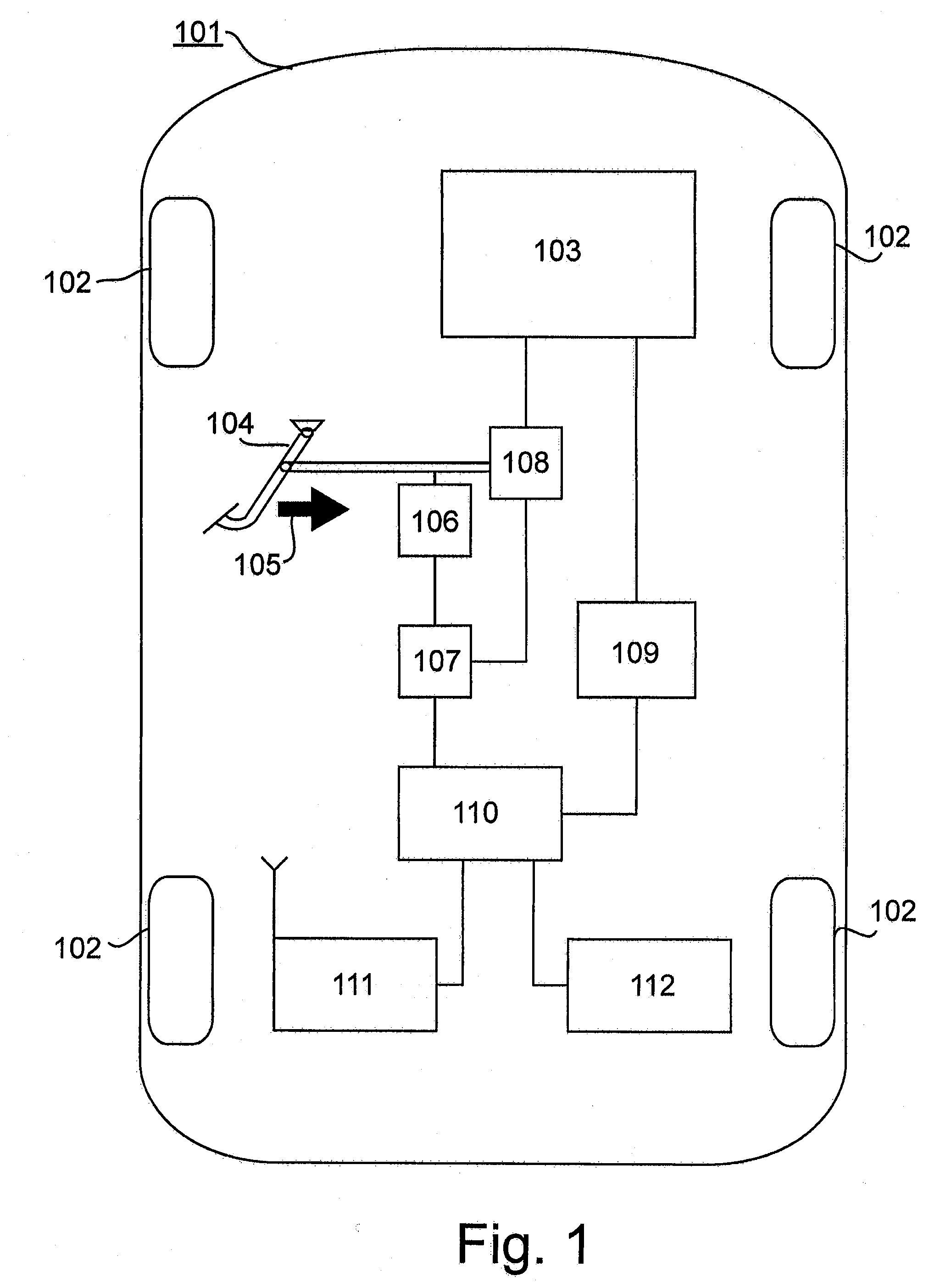
[0026]FIG. 1 is a schematic illustration of a motor vehicle 101 with four wheels 102. The motor vehicle 101 is driven by a drive engine 103, which can be, for example, an internal combustion engine, an electric motor or a hybrid motor. The drive engine 103 generates an engine torque which is transmitted to two or four vehicle wheels 102 via a drive train (not illustrated in the figure) in order to drive these wheels 102. The drive engine 103 is controlled by the driver of the vehicle 101 by means of an accelerator pedal 104. As a rule, the position of the accelerator pedal 104 corresponds to an assigned engine speed request and / or drive torque request by the driver. A change in the position of the accelerator pedal in an activation direction which is illustrated in FIG. 1 by means of an arrow 105 leads here to an increase in the engine speed and / or the drive torque which is made available by the drive engine 103.

[0027]In one configuration, the accelerator pedal 104 is assigned a for...


PUM


Abstract

A method for assisting an operator of a vehicle which is approaching a set of traffic lights which permits a stop line to be crossed in at least one first operating state and does not permit the stop line to be crossed in a second operating state. The method provides that (i) a signal which describes the current operating state of traffic lights and the time period until the operating state changes is received in the vehicle, (ii) in the vehicle, verification is carried out on the basis of the received signal as to whether the vehicle can reach the stop line at a speed from a predefined speed range while the set of traffic lights is in the first operating state, and (iii) a speed of the vehicle is influenced and / or a recommendation for influencing the speed is generated as a function of the result of the verification.

Description

CROSS REFERENCE TO RELATED APPLICATIONS[0001]This application is the U.S. national phase application of PCT International Application No. PCT / EP2008 / 067066, filed Dec. 9, 2008, which claims priority to German Patent Application No. 10 2007 060 603.8, filed Dec. 13, 2007, and German Patent Application No. 10 2008 060 869.6, filed Dec. 9, 2008, the contents of such applications being incorporated by reference herein.FIELD OF THE INVENTION[0002]The invention relates to a method and a device for assisting an operator of a vehicle. In particular, in this context assistance is provided with respect to a set of traffic lights which permits a stop line to be crossed in one operating state and does not permit said stop line to be crossed in a further operating state.BACKGROUND OF THE INVENTION[0003]In road traffic, sets of traffic lights are frequently used to control the flow of traffic. The sets of traffic lights are usually assigned a stop line which a vehicle can pass in a first operatin...

Claims


Application Information

Patent Timeline
IPC IPC(8): B60Q1/00G06F7/00
CPCG08G1/095Y02T10/84G08G1/096725G08G1/096741G08G1/096783B60W50/0097B60W50/14B60W10/04B60W10/18B60W30/143B60W30/18154B60W2050/146B60W2550/22B60W50/16G08G1/096716B60W2555/60
Inventor STAHLIN, ULRICHSWOBODA, ADAMGROTENDORST, THOMAS
Owner CONTINENTAL TEVES AG & CO OHG
Learn More