Pin moor

a pin moor and anchor technology, applied in the field of sewing devices, can solve the problems of difficult device use, difficult closure of safety pins, laborious and laborious implementation, etc., and achieve the effect of convenient and efficient us

Inactive Publication Date: 2011-05-05
IVISON LORETTA
View PDF60 Cites 0 Cited by
  • Summary
  • Abstract
  • Description
  • Claims
  • Application Information

AI Technical Summary

Benefits of technology

[0014]To achieve the foregoing objects, and in accordance with the purpose of the invention as embodied and broadly described herein, a portable, stable, moor for pins, needles, or other sewing implements is provided comprising a moor having a first end and a second end, the first and the second end are connected by a central portion which may be curved, whereby the moor can be positioned on a surface and receive a pin, needle, or other sewing implement to anchor a piece of cloth to the surface of another piece of cloth. The moor or anchor may be partially pierced on any surface or edge, and a plurality of such moors or anchors form a support and positioning network which is very useful and efficient. The moor may be configured in various shapes and include curved portions and planar surfaces. A method for using the moor to secure and position pins and other sewing implements to pieces of cloth is also disclosed.

Problems solved by technology

For example, basting with a needle and thread has been done for many years and is still used by some quilters, although it is very labor intensive and takes hours of time and effort to implement.
The primary difficulties with safety pins is that the safety pins are hard to close and often get in the way of the machine being used or the hand needle when the quilting is being done.
Such device is difficult to use, is inconsistent in operation, and leaves large holes in the fabric.
Further, the plastic tabs shot by such device are difficult to remove from the cloth.
Although pins are very useful, easy to move around, and do not put large holes in the fabric, and are an effective way to hold pieces of cloth together, when used alone, there is nothing to hold them in place.
In fact, this is a significant limitation of using pins or other sewing implements alone.

Method used


Image

  • Pin moor
  • Pin moor
  • Pin moor

Examples


Embodiment Construction

[0024]Reference will now be made in detail to the present preferred embodiments of the invention as illustrated in the accompanying drawings.

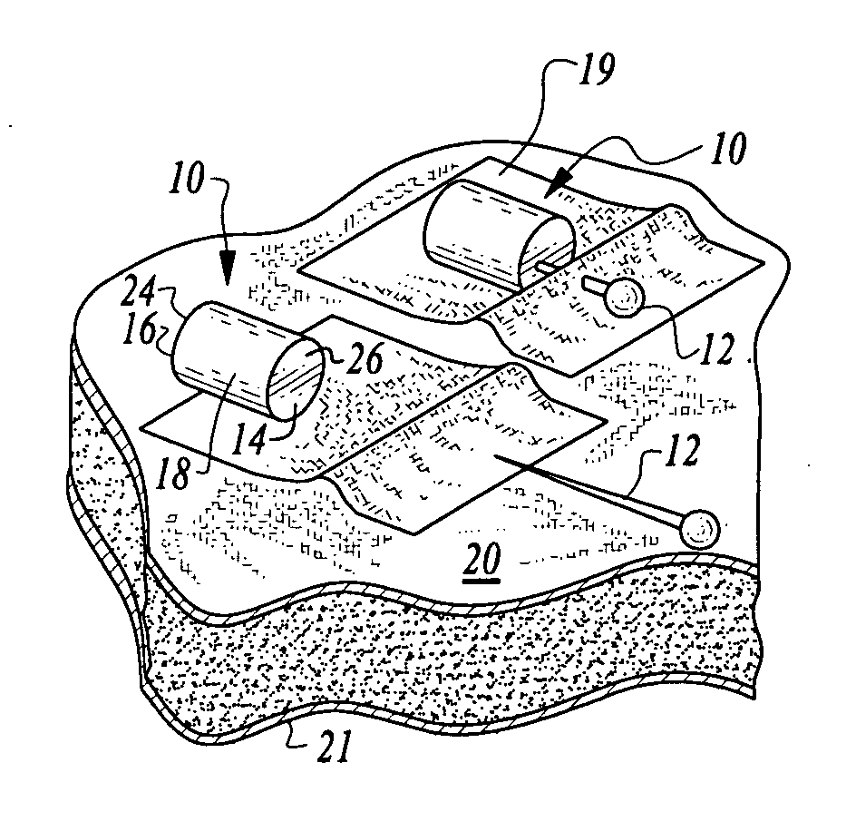
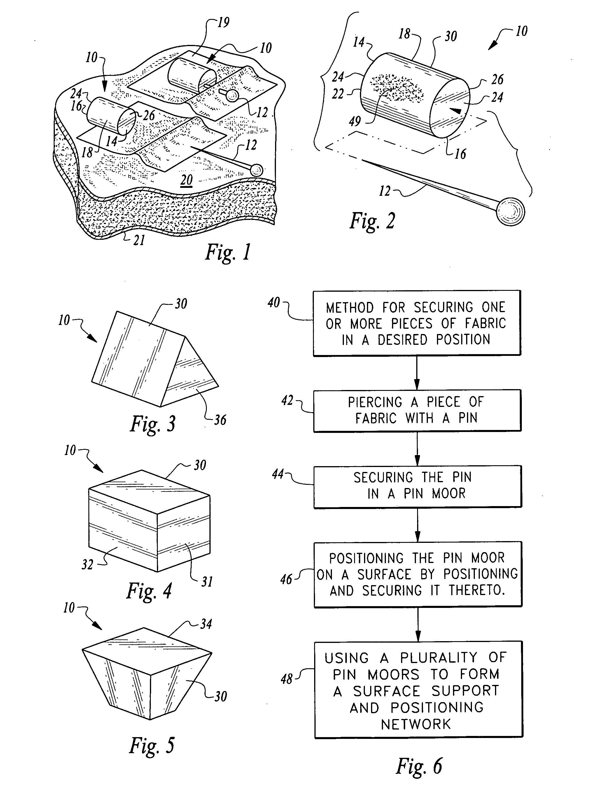
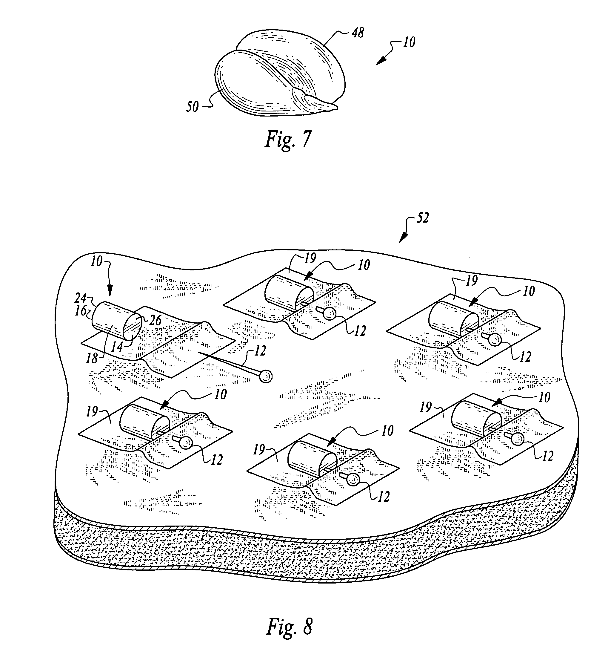
[0025]In accordance with the present invention, there is provided in a preferred embodiment of the invention, a portable, stable, moor or anchor for pins, needles, or other sewing implements, comprising, a moor having a first end and a second end, the first and the second end are connected by a central portion which may be curved, whereby the moor can be positioned on a surface and receive a pin, needle, or other sewing implement to anchor a piece of fabric to the surface. The surface may be any fabric, cloth. vinyl, plastic, or the like. A plurality of such moors or anchors are used to form a surface support and positioning network to aid and facilitate sewing and quilting operations.

[0026]In FIG. 1, a preferred embodiment of pin moor or anchor 10, is shown. Preferably, moor 10, is utilized for receiving and securing pins 12, or other sewing i...


PUM


Abstract

A moor or anchor (10) for pins (12), needles, or other sewing implements, comprising a moor or anchor having a first end and a second end, the first (14) and the second end (16) are connected by a central portion (30) which may be curved (18), whereby the moor or anchor (10) can be positioned on a surface (20) and receive a pin (12), needle, or other sewing implement to anchor a piece of fabric (19) to the surface. The surface (20) may be fabric, cloth, vinyl, plastic, or any other flexible material. The moor or anchor (10) may be configured in various shapes and include curved portions (18) and planar surfaces (26), and color-coded to facilitate use. A plurality of the moors or anchors are used to form a support and positioning network (50). A method for using the moor to secure and position pins and other sewing implements to surfaces such as fabric or other flexible material is also disclosed, allowing the formation of a surface support and positioning network (48).

Description

CROSS REFERENCE TO RELATED APPLICATIONS[0001]This application is a continuation-in-part of and claims priority from co-pending U.S. patent application Ser. No. 11 / 273,239, filed Nov. 14, 2005, and is related to and claims priority from PCT International Patent application PCT / US2006 / 037423 filed Sep. 26, 2006 and corresponding U.S. patent application Ser. No. 11 / 991,757 filed Mar. 10, 2008, and U.S. Provisional Patent Application 61 / 341,864, filed Apr. 6, 2010.BACKGROUND OF THE INVENTION[0002]1. Technical Field[0003]This invention relates to sewing devices for holding and positioning pins or other sewing implements, and more particularly to a pin moor or anchor for securing pins and other sewing implements in a desired position, and for positioning pieces of fabric by creating a network of supporting and positioning anchors or moors on a fabric surface.[0004]2. Background Art[0005]Various devices have been proposed and implemented for holding and positioning articles. Although prior...

Claims


Application Information

Patent Timeline
Patent Type & Authority Applications(United States)
IPC IPC(8): D05B91/12
CPCD05B97/12A41H17/00
Inventor IVISON, LORETTA
Owner IVISON LORETTA
Why Eureka
Try Eureka