Beam alignment

a beam alignment and beam technology, applied in the field of beam alignment, can solve the problems of reducing the level of light, affecting the stability of the beam alignment, and achieving the wrong alignment, so as to reduce the level of light and improve the stability

Active Publication Date: 2019-07-30
FFE
View PDF11 Cites 0 Cited by
  • Summary
  • Abstract
  • Description
  • Claims
  • Application Information

AI Technical Summary

Benefits of technology

[0027]Preferably, the method further comprises, whilst tracing, if no signal is detected or any signal less than an operable threshold is detected at a subsequently projected location, continuing tracing the circumjacent pathway or increasing the size of the circumjacent pathway.
[0052]Advantageously, alignment according to the present invention is quicker, easier and more efficient than manual alignment, and reduces the incidences of wrong alignment. No actual manual alignment of the detector unit is required. Accurate alignment of the centre of the beam to the centre of the reflector is provided. Further, by accurately aligning the centre of the beam to the centre of the reflector, there is a reduction in false alarms caused by movement of the building, this also provides long-term benefits through the life of the installation, as future problems with alignment are minimised or avoided. Advantageously, alignment also conducts a useful cross-reference so as to check that alignment is with the reflector per se and not some other reflective surface. Profiling of the reflective surface of the reflector identifies the shape of the reflective surface, and can flag if an unexpected (unsymmetrical) object is being profiled. A so-called box search provides a useful and efficient search too for locating a reflector is laser targeting has been unsuccessful or not utilised.
[0053]Beam profile is an important consideration in Infrared (IR) beam detectors, especially in reflective-type smoke detectors. This helps to ensure that efficient installation and continued stable operation can be achieved. A flat, wide beam is good at reducing susceptibility to building movement—the beam will naturally move during normal operation as the building shifts over time. If the size of the beam is large compared to the reflector, and the intensity is constant across its width, then once centred this will give the most tolerance to subsequent movement. Further, it is only when the edge of the beam reaches the edge of the reflector that the amount of reflected light is reduced. However, a wider beam is much more difficult to achieve as it disperses light much more and, hence, a more powerful transmitter is required. Conversely, a narrow beam is much more light-efficient, which means that a less powerful transmitter is needed, but the system is much more susceptible to the effects of beam movement after alignment. Accordingly, beam profile is somewhat of a play-off between the size of the illuminated area and the amount of illumination. In a situation where the illuminated area around the reflector is much larger than the reflector, the light itself is relatively dim. In a situation where the illumination is very intense and the illuminated area is essentially the same size as the reflector, there is very little tolerance to the effects of the building (and thereby the beam) moving during normal operation. In a preferred situation, a compromise, the light is of an adequate intensity and the illuminated area is still larger than the reflector. The design of the lens needs to take these factors into consideration and control the beam profile and divergence angle (which controls intensity).

Problems solved by technology

Manual alignment can be a slow and drawn-out process, and it is surprisingly easy, even for professionals using this method, to achieve the wrong alignment—for instance, alignment with a reflective object which is not the reflector per se.
Laser targeting—illumination of the reflector with a visible laser—has led to a reduction in wrong alignment; however, alignment of the laser on the reflector is no guarantee of alignment of the transmitter and the reflector, and the reflector and the receiver.

Method used


Image

  • Beam alignment
  • Beam alignment
  • Beam alignment

Examples


Embodiment Construction

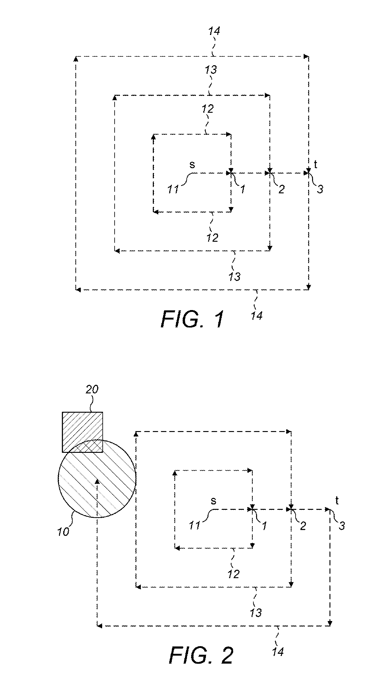
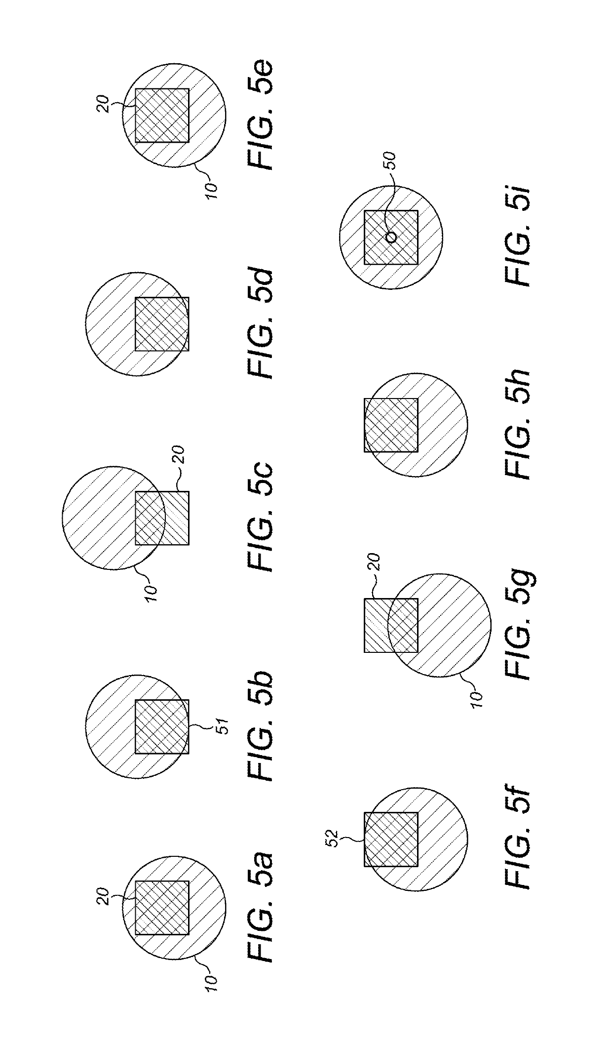
[0061]An overall alignment process has two main steps: firstly, laser targeting of the reflector; and, secondly, an auto-align procedure. In laser targeting, a user remotely maneuvers a detector, using its internal motor, so that an integrated visible laser is pointing at the reflector. The laser is only a rough alignment guide; however, and having the laser on the reflector is no guarantee that the Infrared (IR) beam is also perfectly aligned on the reflector. The auto-align procedure is used to properly align the IR beam on the reflector and has three main steps; search; adjust; and centre. In a preferred embodiment, during the installation procedure, auto-align is automatically initiated after the user has turned off the laser.

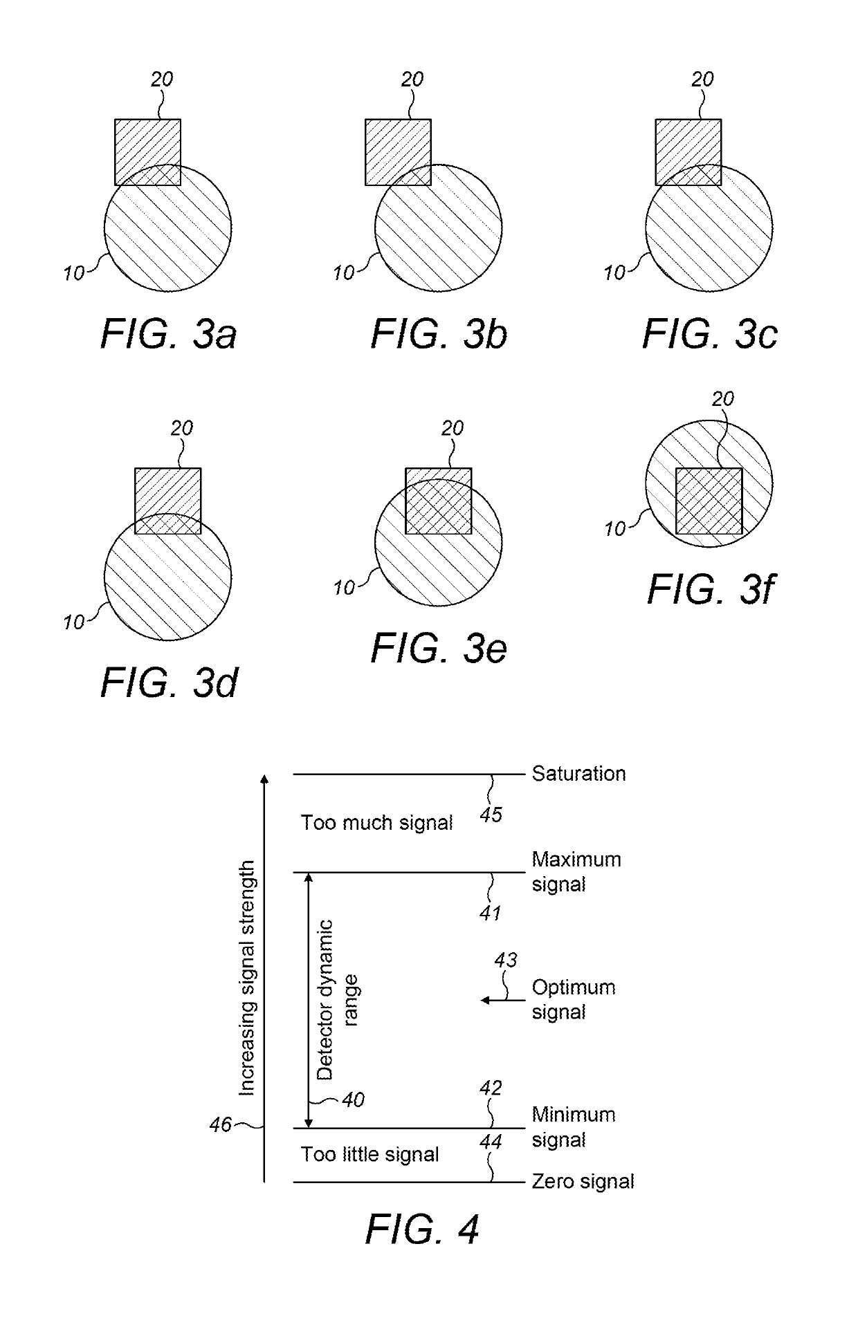
[0062]The auto-align procedure is implemented through an algorithm (which is run by a computer), which algorithm requires a minimum signal level (i.e. a minimum amount of light returned by the reflector) for it to complete correctly. As such, the first cons...


PUM

PropertyMeasurementUnit
sizeaaaaaaaaaa
poweraaaaaaaaaa
thresholdaaaaaaaaaa

Abstract

A method for aligning a projected beam on a reflector in a reflective-type beam detector, the method including adjusting the projected beam so as to: project on to substantially all, if not all, of a reflective surface of the reflector; or project on to at least a portion of a reflective surface of the reflector until a constant, or within a predetermined threshold of a constant, signal is received from the reflector; and detecting one or more edges of the reflective surface of the reflector and thereby: centering the projected beam, so as to align an approximate center of the projected beam on, or within a predetermined threshold of, an approximate center of the reflective surface of the reflector; and / or determining a shape or profile of the reflector.

Description

CROSS-REFERENCE TO RELATED APPLICATION[0001]This patent application claims priority from UK Patent Application No. GB1610488.7, filed the 16 Jun. 2016, the disclosure of which is incorporated by reference herein in its entirety.FIELD OF THE INVENTION[0002]The present invention relates to beam alignment. In particular, the invention relates to a method for aligning a projected beam on a reflector in a reflective-type beam detector, a method for searching for and projecting a beam on to a reflector in a reflective-type beam detector, and apparatus associated with the methods.BACKGROUND OF THE INVENTION[0003]In summary, a reflective optical beam smoke detector system has a detector unit, which includes both a transmitter and a receiver, and a retro-reflector. The detector unit and the reflector are placed opposite each other at opposing ends of a volume to be protected and monitored. The transmitter projects a beam, in this example an Infrared (IR) beam, on to the retro-reflector which...

Claims


Application Information

Patent Timeline
Patent Type & Authority Patents(United States)
IPC IPC(8): G01N21/17G01B11/24G01J5/08G08B17/103G08B29/20G01J5/00G08B17/10G08B29/18
CPCG01J5/0896G01B11/24G01J5/0803G08B29/20G08B17/103G08B29/18G01J2005/0048G08B17/10G01N21/53G08B17/12G08B29/24G01J5/80
Inventor ANDELIN, JACOBDIBDEN, GARETHPERCH, MARCUS
Owner FFE
Why Eureka
Try Eureka