Interference filter, optical sensor, and optical module

a technology of interference filter and optical sensor, applied in the direction of interferometric spectrometry, optical radiation measurement, instruments, etc., can solve the problems of stress in the adhesive applied portion, warpage of the substrate, and inability to control the thickness of the adhesive layer, etc., to achieve accurate analysis of light inciden

Inactive Publication Date: 2011-06-02
SEIKO EPSON CORP
View PDF5 Cites 10 Cited by
  • Summary
  • Abstract
  • Description
  • Claims
  • Application Information

AI Technical Summary

Benefits of technology

[0011]An advantage of some aspects of the invention is to provide an interference filter, an optical sensor, and an optical module having high spectral precision.

Problems solved by technology

For example, when the substrates are bonded to each other by forming an adhesive layer formed of an adhesive between the substrates, it is disadvantageously difficult to control the thickness of the adhesive layer and hence difficult to maintain the reflection films parallel to each other.
When the adhesive applied into the adhesive groove is used to bond the substrates to each other as described above, however, volume shrinkage that occurs when the adhesive hardens induces stress in the adhesive applied portion and the stress warps the substrates.
When the first substrate warps into the adhesive groove, the balance among the forces acting on the entire first substrate becomes unstable.
As a result, the pair of reflection films cannot disadvantageously be maintained parallel to each other.
The spectral precision of the interference filter is therefore disadvantageously poor.
If each of the warp reduction grooves is disposed in a position close to the second gap formation region, the slight reaction force described above is conceivably transferred to the first gap formation region and warps the first gap formation region and makes the balance among the forces in the first gap formation region unstable.

Method used


Image

  • Interference filter, optical sensor, and optical module
  • Interference filter, optical sensor, and optical module
  • Interference filter, optical sensor, and optical module

Examples


first embodiment

[0044]A colorimetry module as an optical module of a first embodiment according to the invention will be described below with reference to the drawings.

1. Overall Configuration of Colorimetry Module

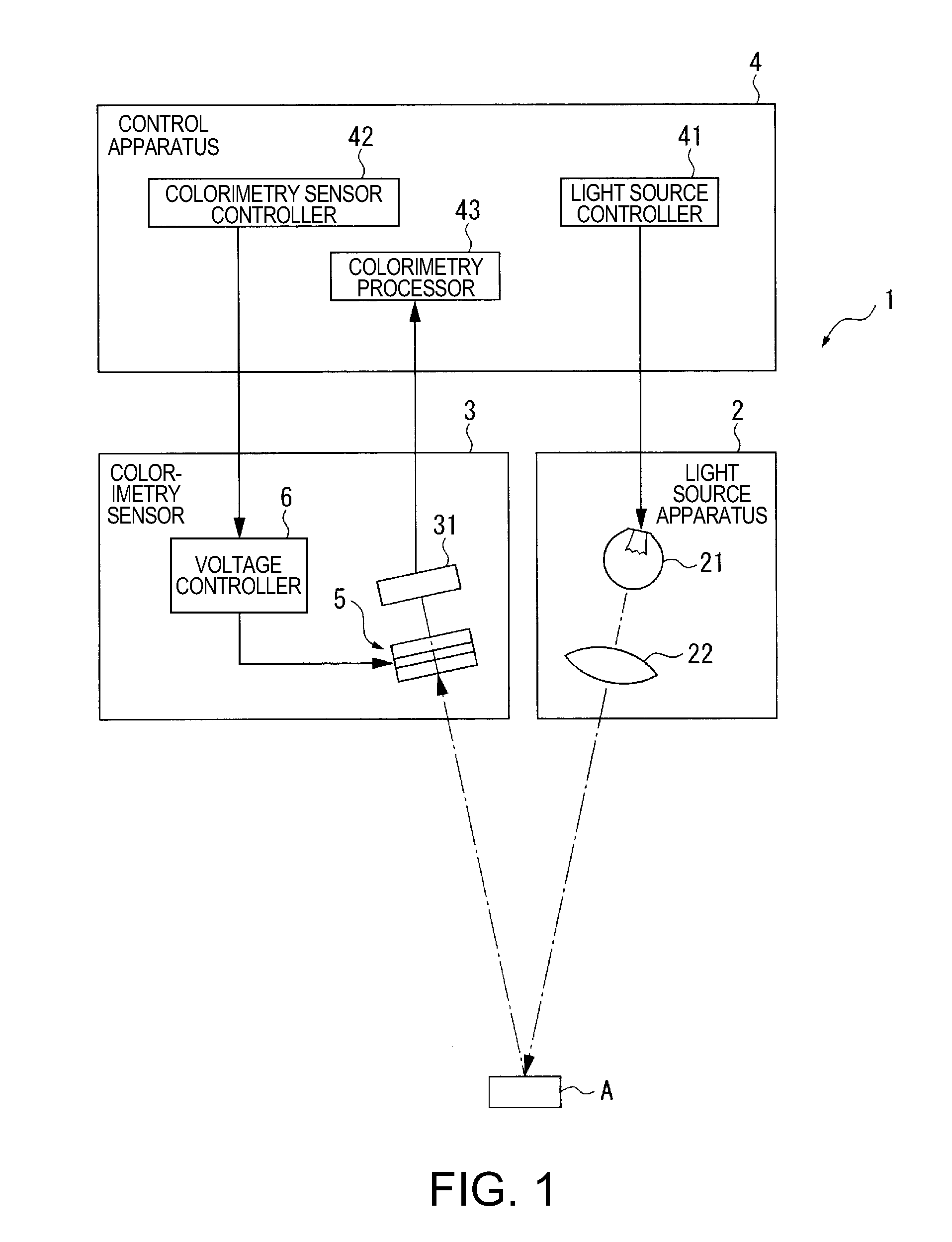
[0045]FIG. 1 shows a schematic configuration of the colorimetry module of the first embodiment according to the invention.

[0046]The colorimetry module 1 includes a light source apparatus 2 that emits light toward an object to be inspected A, a colorimetry sensor 3, which is an optical sensor according to the invention, and a control apparatus 4 that controls the overall action of the colorimetry module 1, as shown in FIG. 1. When the object to be inspected A reflects the light emitted from the light source apparatus 2 and the colorimetry sensor receives the reflected light to be inspected, the colorimetry module 1 analyzes and measures the chromaticity of light to be inspected, that is, the color of the object to be inspected A based on a detection signal outputted from the colorimetry se...

second embodiment

[0124]A colorimetry module of a second embodiment according to the invention will next be described.

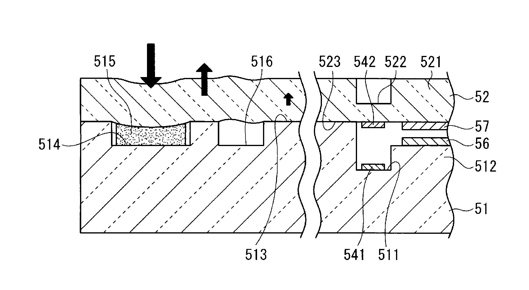
[0125]The colorimetry module of the second embodiment differs from the colorimetry module 1 of the first embodiment only in terms of the shape of the warp reduction grooves 516 in the etalon 5. Only the configuration of the fixed substrate of the etalon will be described.

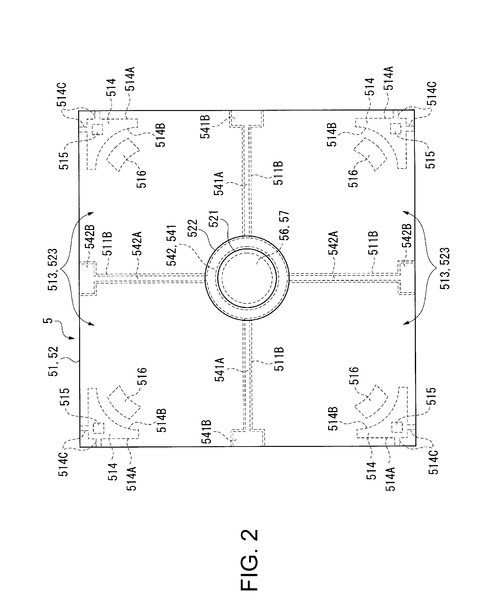
[0126]FIG. 9 is a plan view showing the fixed substrate 51 of an etalon 5A of the second embodiment. In the following description, the same components as those in the first embodiment have the same reference characters, and descriptions of these components will be omitted or simplified.

[0127]As shown in FIG. 9, in the etalon 5A of the second embodiment, each warp reduction groove 516A has a substantially rectangular shape in the etalon plan view, and a plurality of warp reduction grooves 516A are provided along a curve L that substantially follows the inner edge 514B of each of the adhesive grooves 514. The distance b...


PUM


Abstract

An interference filter includes: a first substrate; a second substrate that faces one side of the first substrate and is bonded to the first substrate; a first reflection film formed on the side of the first substrate that faces the second substrate; and a second reflection film provided on the second substrate and faces the first reflection film, the first substrate including a first gap formation region in which the first reflection film is disposed and which is not contact with the second substrate, and wherein the first substrate and the second substrate are adhesively bonded to each other with the adhesive applied into the adhesive grooves with the first bonding region and the second bonding region bonded to each other.

Description

[0001]The entire disclosure of Japanese Patent Application No. 2009-271234, filed Nov. 30, 2009 is expressly incorporated by reference herein.BACKGROUND[0002]1. Technical Field[0003]The present invention relates to an interference filter that separates light of a predetermined wavelength from incident light, an optical sensor including the interference filter, and an optical module including the optical sensor.[0004]2. Related Art[0005]There have been known interference filters that transmit or reflect only a predetermined wavelength light from incident light (see JP-A-2009-134027, for example).[0006]JP-A-2009-134027 describes an optical device (interference filter) having a pair of substrates facing each other and having reflection films formed on the surfaces of the substrates that face each other. In the interference filter of this type, a gap is formed between the pair of reflection films, and the dimension of the gap determines the wavelength of light that can be separated.[000...

Claims


Application Information

Patent Timeline
Patent Type & Authority Applications(United States)
IPC IPC(8): G02B5/28G02B1/10G01B9/02G01J3/26G01J3/50G02B26/00
CPCG01J3/26G02B26/001G01J3/51
Inventor NISHIMURA, TERUYUKISANO, AKIRA
Owner SEIKO EPSON CORP
Why Eureka
Try Eureka