Illumination Device Comprising Multiple LEDs

a technology of leds and illumination devices, which is applied in the direction of electric variable regulation, process and machine control, instruments, etc., can solve the problems of increasing power supply costs, affecting the quality of light output,

Inactive Publication Date: 2011-06-09
KONINKLIJKE PHILIPS ELECTRONICS NV
View PDF6 Cites 65 Cited by
  • Summary
  • Abstract
  • Description
  • Claims
  • Application Information

AI Technical Summary

Problems solved by technology

A problem with LEDs is the power supply; it is noted that the power supply in a car is provided by the car's battery, typically providing a voltage in the order of 6 V or 12 V or 24 V. For a LED to produce light, it requires a current to pass through it in one direction (from anode to cathode); current flow in the opposite direction is blocked.
Thus, the costs of power supply increase.
A problem when powering a LED or a string of LEDs directly from a car battery is that the supply voltage may change substantially with time. FIG. 1 is a graph showing a relationship between supply voltage and LED current.

Method used


Image

  • Illumination Device Comprising Multiple LEDs
  • Illumination Device Comprising Multiple LEDs
  • Illumination Device Comprising Multiple LEDs

Examples


Embodiment Construction

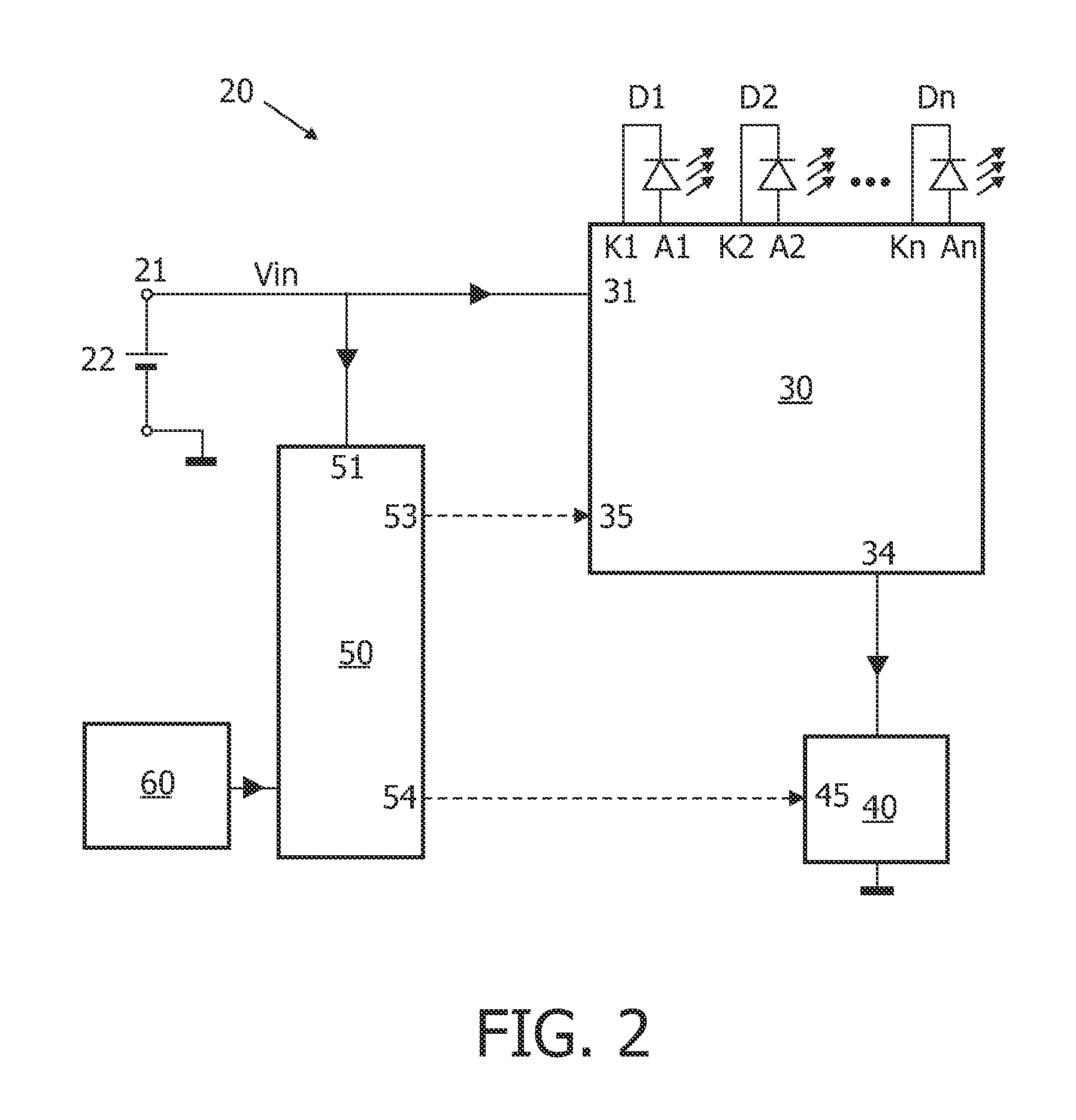
[0020]FIG. 2 is a block diagram schematically illustrating an illumination device 20 according to the present invention. The device 20 has an input 21 for connection to a car battery 22 (or, in practice, a power bus connected to the battery), supplying 12 V DC.

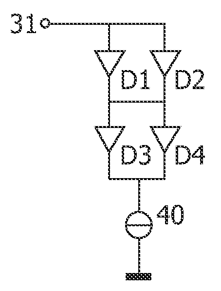
[0021]D1, D2, . . . Dn indicate respective groups of LEDs. Each group may consist of only one LED. Each group may also comprise a plurality of LEDs connected in series and / or in parallel. It is preferred that the groups are mutually identical, but this is not essential. For sake of simplicity, each group will hereinafter be discussed as if it is identical to one single LED.

[0022]The LEDs D1, D2, . . . Dn have their terminals connected to output terminals A1 and K1, A2 and K2, . . . An and Kn of a switch matrix 30 which comprises a plurality of N switches S1-SN, as will be discussed later. The switch matrix 30 has an input 31 coupled to the input 21 such as to receive the bus DC voltage.

[0023]The device 20 further has a control...


PUM


Abstract

A light generating device (20) comprises: —an input for receiving a DC input voltage (Vin) of varying magnitude; —a controllable current source (40); —a switch matrix (30) comprising a plurality of controllable switches (S1-SN); —a plurality of n LEDs (D1, D2, . . . Dn) connected to output terminals of the switch matrix (30); —a controller (50) controlling said switches and controlling the current generated by the current source dependent on the momentary value of the DC input voltage (Vin). The controller is capable of operating in at least three different control states. In a first control state all LEDs are connected in parallel. In a second control state all LEDs are connected in series. In a third control state at least two of said LEDs are connected in parallel while also at least two of said LEDs are connected in series.

Description

FIELD OF THE INVENTION[0001]The present invention relates in general to a lighting device comprising a plurality of LEDs. The present invention relates particularly to a device for use in automobiles, suitable for providing tail light, brake light or turn signal light.BACKGROUND OF THE INVENTION[0002]In general, the use of LEDs for illumination purposes is known. A problem with LEDs is the power supply; it is noted that the power supply in a car is provided by the car's battery, typically providing a voltage in the order of 6 V or 12 V or 24 V. For a LED to produce light, it requires a current to pass through it in one direction (from anode to cathode); current flow in the opposite direction is blocked. When driven with current having the correct direction, a voltage drop develops over the LED which is substantially independent of the LED current. Within margins, the LED current can be varied, and the light output will be substantially proportional to this current. When it is desira...

Claims


Application Information

Patent Timeline
Patent Type & Authority Applications(United States)
IPC IPC(8): H05B37/02H05B44/00
CPCH05B33/083H05B33/0827H05B45/44
Inventor SAUERLAENDER, GEORGRADERMACHER, HARALD JOSEF GUNTHER
Owner KONINKLIJKE PHILIPS ELECTRONICS NV
Why Eureka
Try Eureka