
Posterior Lumbar Retractor System

Inactive Publication Date: 2011-06-09
THALGOTT JOHN +5
View PDF13 Cites 42 Cited by
  • Summary
  • Abstract
  • Description
  • Claims
  • Application Information

AI Technical Summary

Benefits of technology

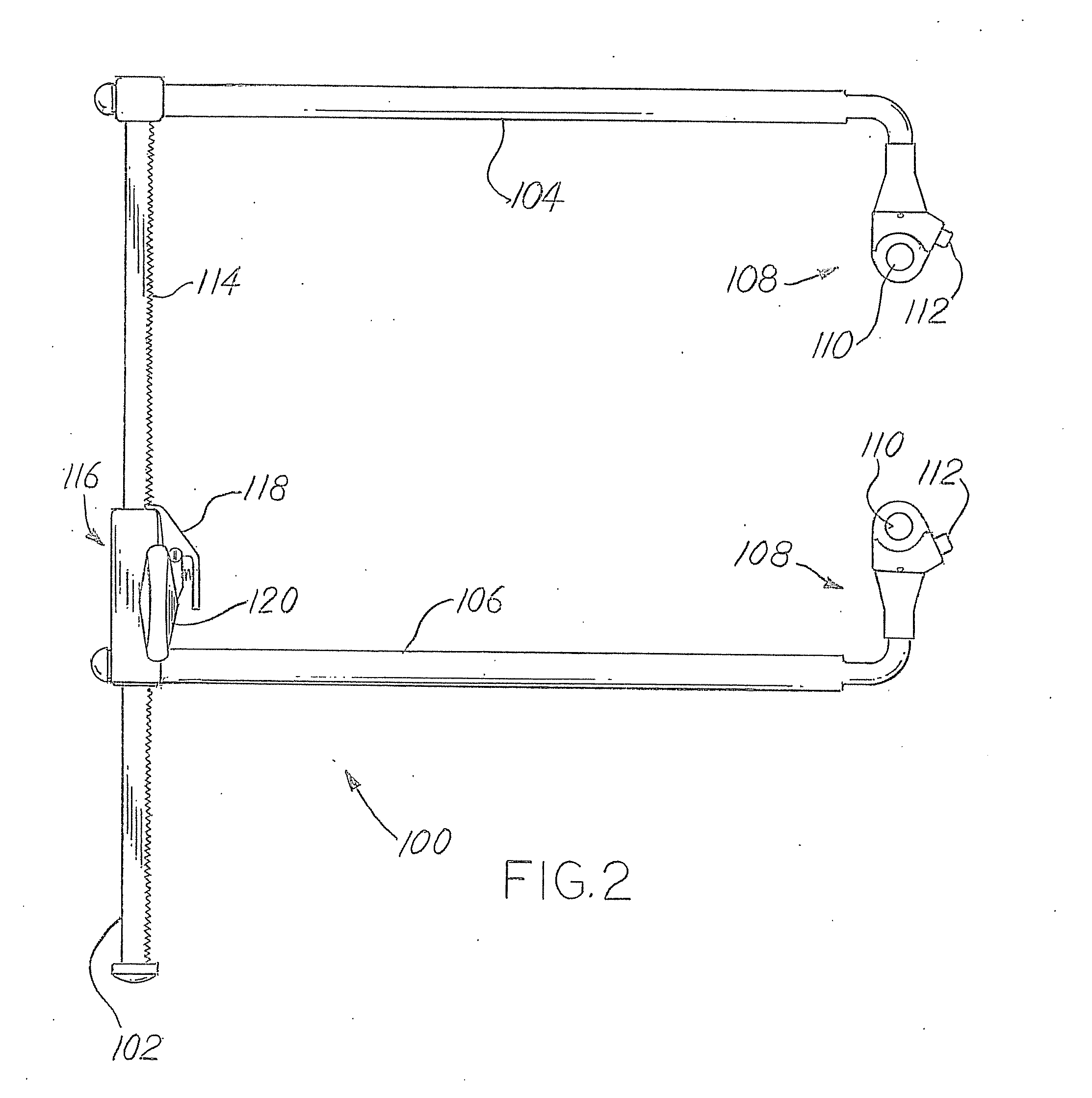
[0011]In certain embodiments, the first securement feature includes a fixed arm that is fixed relative to the frame, and the second securement feature includes a movable arm that is movable with respect to the frame. Further, in certain embodiments, the frame includes a spreader bar that extends between the first and second securement features. The spreader bar includes teeth that form a rack, and the second securement feature includes a pinion that cooperates with the rack to facilitate lateral movement of the movable arm with respect to the fixed arm.

Problems solved by technology

Such a fixed angle limits the flexibility of the system to provide different shapes of access areas.

Method used


Image

  • Posterior Lumbar Retractor System
  • Posterior Lumbar Retractor System
  • Posterior Lumbar Retractor System

Examples


Embodiment Construction

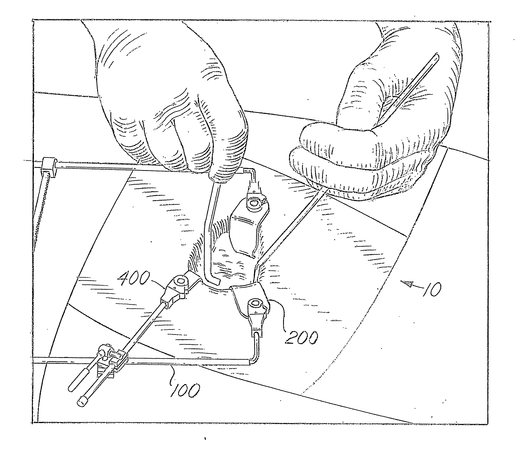
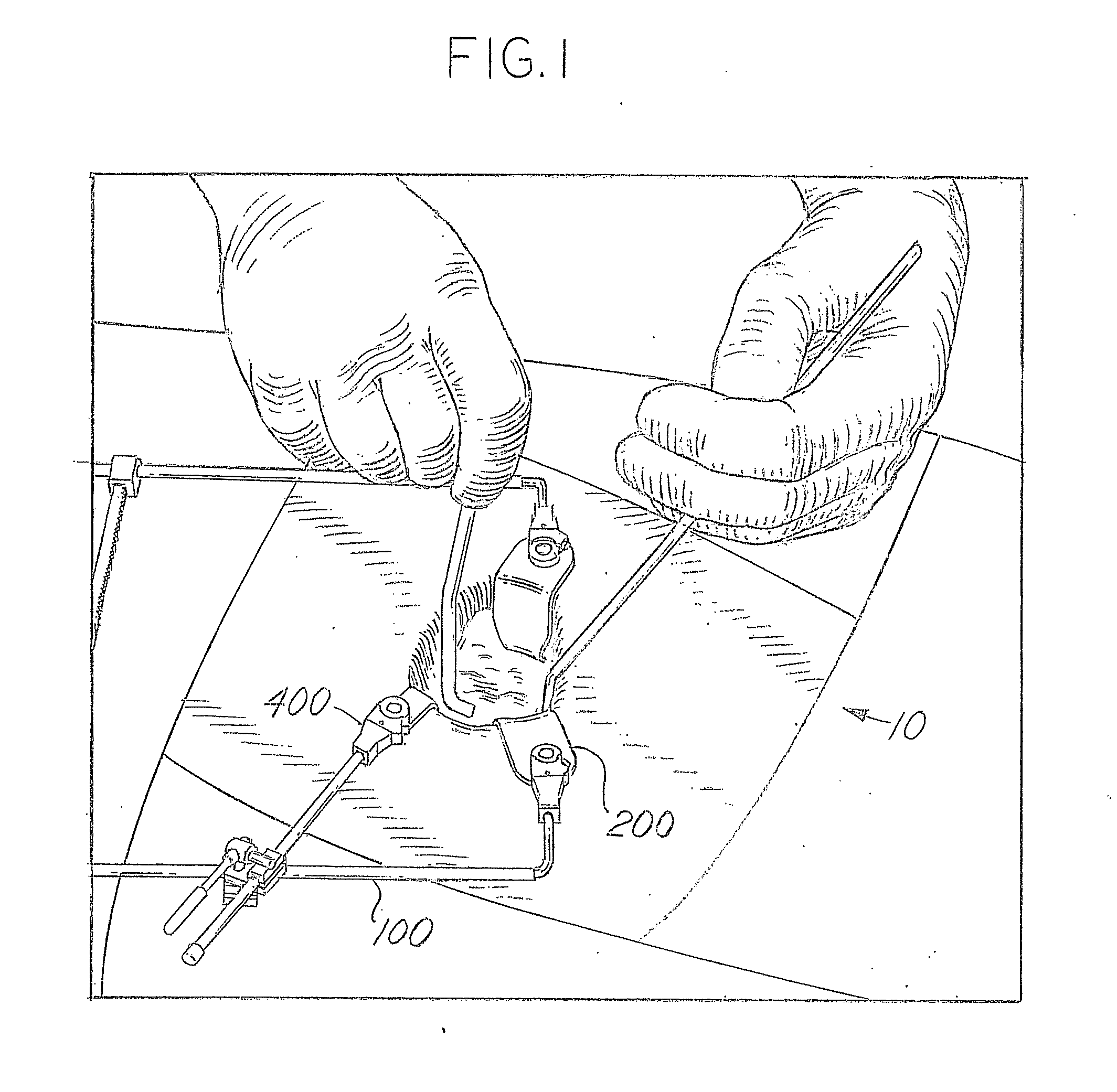
[0028]FIG. 1 illustrates an embodiment of a posterior retractor system 10 formed in accordance with an embodiment of the present invention. In the illustrated embodiment, the retractor system 10 includes a blade spreader frame 100, a plurality of retractor blades 200, 300, and an adjustment arm 400. The various components of the retractor system 10 may be made, for example, of stainless steel. While an embodiment particularly well adapted for posterior lumbar surgery is discussed below and illustrated in the figures, the disclosed technology is not so limited and may be used for other procedures as well.

[0029]FIG. 2 illustrates an embodiment of a blade spreader frame 100 formed in accordance with an embodiment of the present invention. The blade spreader frame 100 includes a spreader bar 102, a first arm 104, and a second arm 106. The blade spreader frame 100 may be similar in certain regards to the blade spreader described in U.S. patent application Ser. No. 12 / 433,226, titled “Hin...


PUM


Abstract

A retractor system includes a frame and first and second retractor blades. The frame includes first and second securement features. At least one of the first and second securement features is movable with respect to the frame when the at least one of the first and second securement features is mounted to the frame. The first and second retractor blades each have a distal portion and a proximal portion. The proximal portions of the first and second retractor blades are configured to be secured proximate to the first and second securement features respectively, such that the first and second retractor blades may be positioned in a first position wherein the first and second retractor blades are laterally opposed. A movement of the at least one securement feature that is movable with respect the frame adjusts the angle of at least one of the retractor blades, wherein the at least one of the retractor blades may be adjusted between a first angle less than 90 degrees to horizontal and second angle greater than 90 degrees to horizontal.

Description

CROSS-REFERENCE TO RELATED APPLICATION[0001]The present application makes reference to, claims priority to, and claims benefit of U.S. Provisional Application No. 61 / 266,373, entitled “Posterior Lumbar Retractor System,” Attorney Docket No. 22698US01, filed Dec. 3, 2009, the complete subject matter of which is hereby incorporated by reference in its entirety.STATEMENT REGARDING FEDERALLY SPONSORED RESEARCH OR DEVELOPMENT[0002]None.BACKGROUND OF THE INVENTION[0003]The present invention relates to surgical apparatus for retracting anatomy to provide exposure of an operative site, and more particularly relates to retraction apparatus providing improved access to an operative site for a posterior lumbar procedure.[0004]In surgical operations, retraction devices are used to properly access internal organs and bone structures. Retraction devices are generally designed to hold back the anatomy in the immediate area of the operative site to enable a surgeon to have both an optimal view of t...

Claims


Application Information

Patent Timeline
IPC IPC(8): A61B1/32
CPCA61B17/02A61B1/32A61B17/0206A61B2017/0256
Inventor THALGOTT, JOHNNOWAK, STEVEDELICKTA, JOSHMARTIN, CHRISTOPHER T.FARLEY, DANIEL K.ZALUCHA, STEPHANIE
Owner THALGOTT JOHN
Learn More