Switching device failure detection system and method for multilevel converters

Active Publication Date: 2011-06-16
GENERAL ELECTRIC CO
View PDF4 Cites 14 Cited by
  • Summary
  • Abstract
  • Description
  • Claims
  • Application Information

AI Technical Summary

Problems solved by technology

For example if there is large power loss within the switching device due to electrical stress or overcurrent, the switching device overheats and it may lead to thermal breakdown of the switching device.
Similarly, when an inductive load or inductive current is switched off, the switching device may observe overvoltage resulting into voltage breakdown of the switching device.
Once a switching device is broken down or destroyed due to overheat or overvo

Method used


Image

  • Switching device failure detection system and method for multilevel converters
  • Switching device failure detection system and method for multilevel converters
  • Switching device failure detection system and method for multilevel converters

Examples


Example

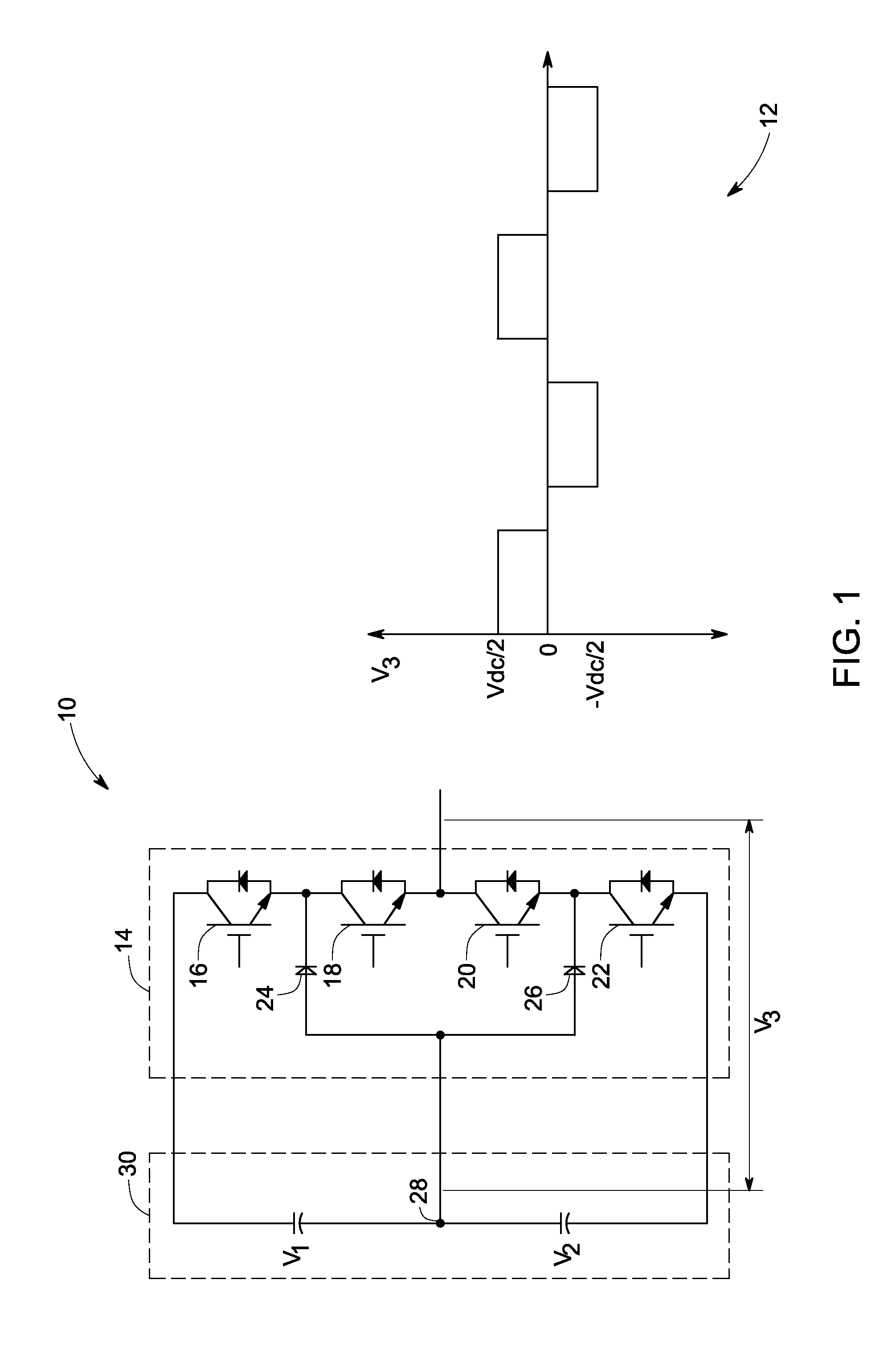
[0017]As discussed in detail below, embodiments of the present invention enable a multilevel converter to convert a direct current (DC) power into an alternating current (AC) power with a switching device fault detection scheme. For example, in a three level Neutral Point Clamped (NPC) converter, a key failure mode exists when a switching device (16, 18, 20, or 22 of FIG. 1) or a clamping diode (24 or 26 of FIG. 1) fails short. Under this condition, one half of the DC link, V1 or V2 in FIG. 1, is charged to the peak line-to-line voltage of the machine or grid side voltage. This value is typically higher than the maximum allowed blocking voltage of the switching devices and the capacitors. In this case, other switching devices or clamping diodes may be stressed in terms of voltage or current beyond their capability. Hence, this will cause additional switching devices, in particular switching devices in phase legs connected to the same DC bus, to fail after the failure of the initial ...


PUM


Abstract

A multilevel converter includes a plurality of phase legs each having at least two inner switching devices, at least two outer switching devices, at least two clamping diodes, a split DC link and a switching device failure detection circuit. The switching device failure detection circuit includes a logic module for each of the switching devices, a voltage calculation module and a failure detection algorithm. The logic module generates a blocking state logic signal by comparing a switching device voltage and a threshold reference voltage and the voltage calculation module determines an expected voltage blocking state for each of the switching devices based on the gate drive signals of the switching devices and an output current direction. The failure detection algorithm detects a failure condition in any of the switching devices based on the blocking state logic signals and the expected voltage blocking states of the switching devices.

Description

BACKGROUND[0001]This invention relates to a method for detection of switching device failure conditions in a multilevel converter.[0002]Multilevel converters (e.g. neutral point clamped converters) are generally used in high power industrial applications such as variable speed drive (VSD) systems or in energy conversion applications such as a solar (or photovoltaic) power generation systems, wind turbine generators or marine and hydrokinetic power generation systems. The general function of the multilevel converter is to synthesize a sinusoidal voltage by several levels of voltages, typically obtained from capacitor voltage sources. A three level converter includes two capacitor voltages in series with the center tap as the neutral. Each phase leg of the three-level converter has two pairs of switching devices in series. The switching device is bidirectional in current, often realized as anti-parallel connection of a unidirectional electronic switching device (e.g. IGBT, IGCT) and a...

Claims


Application Information

Patent Timeline
IPC IPC(8): G01R31/26
CPCG01R31/42H03K17/18H02M7/487H02M1/32
Inventor SOLDI, PAOLOROESNER, ROBERTSCHROEDER, STEFAN
Owner GENERAL ELECTRIC CO
Why Eureka
Try Eureka