Integrated tire repair multi tool with folding pliers

Inactive Publication Date: 2011-06-30
EUBANKS CORMAC
4 Cites 0 Cited by

AI-Extracted Technical Summary

Problems solved by technology

Secondly, the user must clean the puncture of any additional debris so that the tire plug seats properly.
There are two problems with the currently available tools and kits.
First, on most kits the tool to clean the hole and the tool to insert the plug are separate items meaning the individual tools can be lost or misplaced.
This is less convenient than an integrated solution in which all the components are attached to one another.
Secondly, none of the available kits include either a method of extracting the debris that punctured the tire, nor the means to trim the excess plug after it has been inserted.
U.S. Pat. No. 6,170,361 (Yates) All in One Tire Repair Tool has the means to insert a plug and stores the plugs in the handle, but has no means to remove debris from the tire nor a means to trim the excess plug material after the plug is inserted, nor a means to rasp the puncture.
U.S. Pat. No. 4,930,377 (Lester) Tire Repair Kit contains the means to install the plug and to expand the puncture if necessary, but the different tools must be interchanged manually which is inconvenient.
Additionally, as separate components, the individual parts c...

Abstract

An improved tire repair tool having a pair of pliers, with integrated cutters, a rasp for cleaning a tire puncture, a tool for inserting a cylindrical tire plug, and a means to store tire plugs within the assembly. The nominally channel shaped handles of the pliers have first and second ends. The first end of the handles are pivotally mounted to a pair of plier jaws which can be used to remove debris from a tire. The rasp and the means for inserting tire plugs are pivotally mounted to to the second end of one of the handles and can be moved between a stowed position and open position. The rasp and tool for inserting tire plugs are lockable in the stowed and open position in such a way to allow the rasp and insertion tool to rotate into a deployed position where they can be used. The second handle contains a means to store tire plugs.

Application Domain

PliersTyres +1

Technology Topic

RaspEngineering +1

Image

  • Integrated tire repair multi tool with folding pliers
  • Integrated tire repair multi tool with folding pliers
  • Integrated tire repair multi tool with folding pliers

Examples

  • Experimental program(1)

Example

First Embodiment
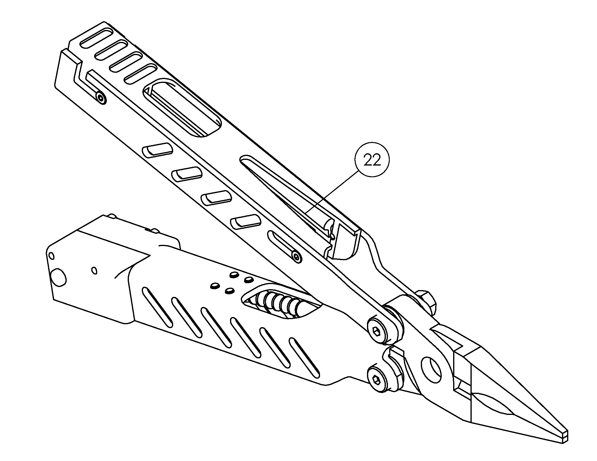
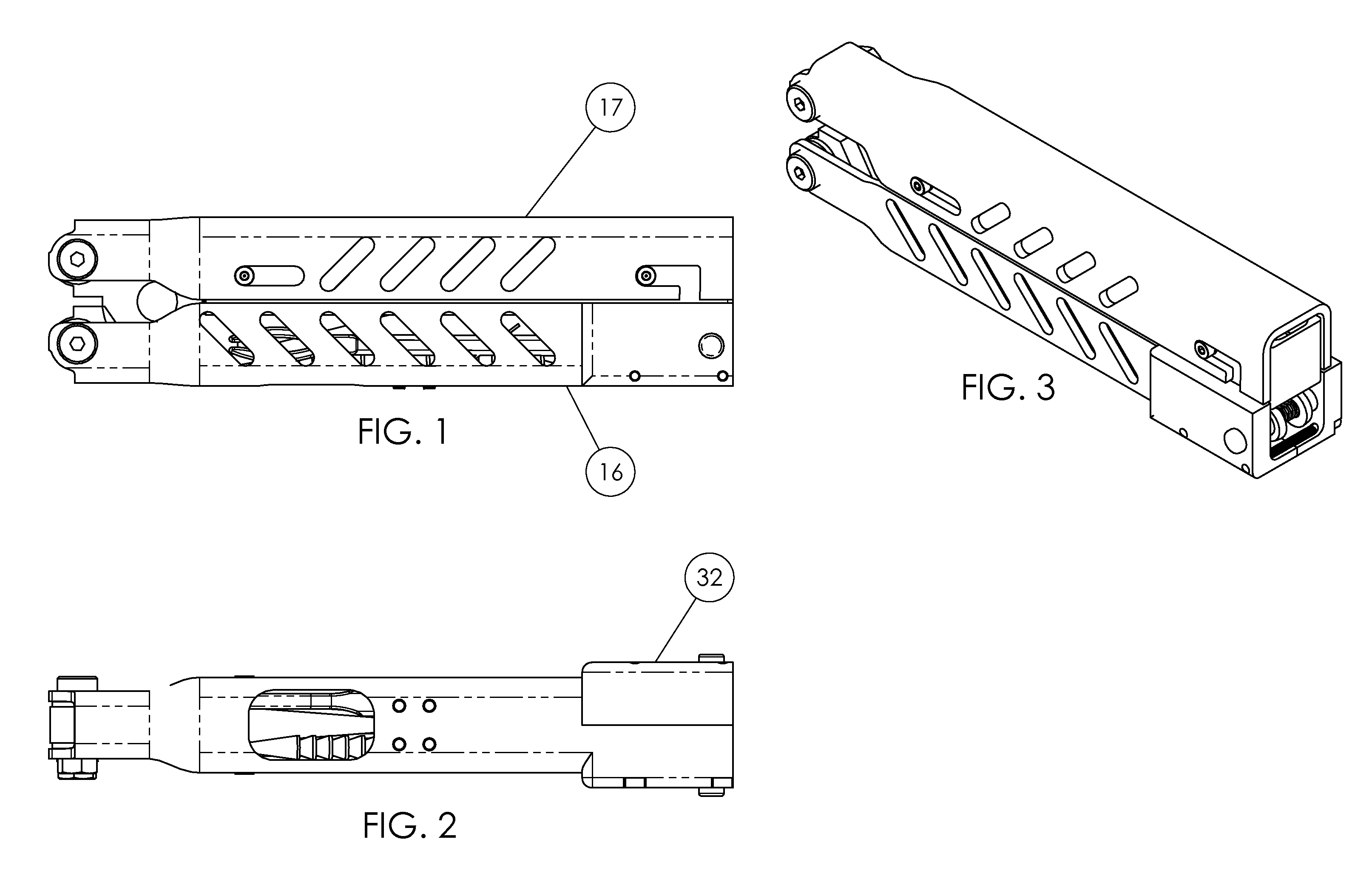
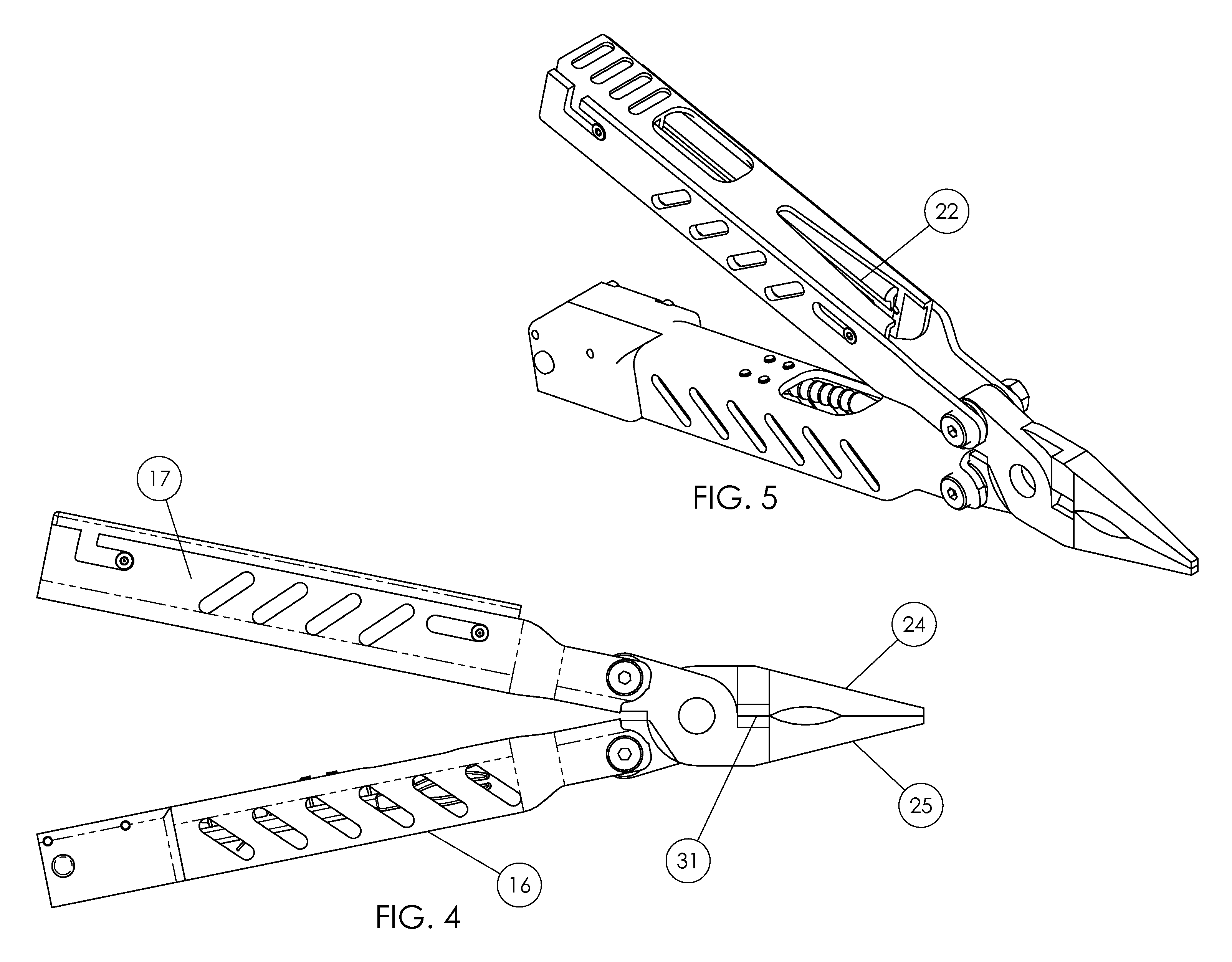
[0052]An all-in-one tire repair tool for insertion of a plug into an injury in a tubeless tire. The tool comprises two nominally channel-shaped handles (16&17). Pliers comprising first and second plier halves (24&125) pivotally mounted to each other, with said plier halves being pivotally mounted to said first ends of said handles; and wherein said folding multi-tool is foldable between a closed, compact configuration in FIG. 1. and an opened, extended configuration for operating said pliers in FIG. 4. The pliers are used to remove the debris (nail, screw, etc) from the damaged tire.
[0053]The first of the handles, Handle, Tire Tools (16) contains nested within the open side a Rasp (18) which is pivotally mounted to the second end of said handle. The rasp, when in the deployed position in FIG. 7 is used to clean a puncture in a tire to ensure the plug, once inserted, remains in the tire. The Handle, Tire Tools also contains a fork (19) also pivotally mounted to the second end of the handle. The fork, when in the deployed position in FIG. 6 can be used to insert the nominally cylindrical tire plug by inserting the plug between the tines of the fork, inserting the fork and plug into the puncture then quickly removing the fork, leaving the plug in place in a folded orientation. In this embodiment, the Rasp and Fork are sandwiched in the handle between the Handle, Tire Tools and the Cap, Handle (32). The Cap, Handle as a separate part from the Handle, Tire Tools allows the tool to be assembled.
[0054]The Rasp (18) contains a U-shaped pocket (30) at the ends of which contain a pair of deeper countersunk pockets as shown in FIG. 10 and shown in cross section in FIG. 11. With the rasp in the stowed position, Button, Rasp, Locking (21) is held in in a nominally outward position in a counterbored pocket (28) by a compression spring (26). With this button in this outward position the rasp is unable to rotate around the pivot axis. To release the rasp, the user pushes the Button, Locking, Rasp (21) inward which moves the button out of the counterbored pocket into a shallower u-shaped pocket (30). The rasp is then able to rotate about the pivot axis (29). Once the rasp rotates into the deployed position the button is forced outward by the compression spring into the locking counterbore pocket (27) locking the rasp in the deployed position which prevents the rasp from rotating during use while cleaning the injury.
[0055]The Fork (19) contains a U-shaped pocket (36) at the ends of which contain a pair of deeper countersunk pockets as shown in FIG. 12 and shown in cross section in FIG. 16. With the fork in the stowed position, Button, Fork, Locking (20) is held in in a nominally outward position in a counterbored pocket (34) by a compression spring (26). With this button in this outward position the fork is unable to rotate around the pivot axis. To release the fork, the user pushes the Button, Locking, Fork (20) inward which moves the button out of the counterbored pocket into a shallower u-shaped pocket (36). The fork is then able to rotate about the pivot axis (35). Once the fork rotates into the deployed position the button is forced outward by the compression spring into the locking counterbore pocket (33) locking the fork in the deployed position which prevents the rasp from rotating during use while inserting the tire plug.
[0056]The second of the handles, Handle, Plug holding (17) contains a Tray, Tire Plug Holding (23) which has two pairs of protruding features shown in this embodiment as socket head cap screws. These protruding features sit in a pair of slots in the Handle, Plug Holding (17). The Straight Slot (37) allows the Tray to slide within the Handle, Plug holding. The second pair of protruding features sit in an L-shaped Slot (38) also in the Handle, Plug Holding (23). When the user slides the tray backwards as indicated by the arrow in FIG. 14, the Tray, Tire Plug Holding is able to pivot into an open position as shown in FIG. 15 so the Tire Plugs (22) can be removed.
Operation
Preferred Embodiment
Removing the Debris:
[0057]The assembly is nominally in the closed position with the rasp and the fork in the stowed position (FIG. 1) To remove the debris from the tire, the user unfolds the handles (16&17) (FIG. 5) and uses the plier jaws (24&25) to grab and extract the debris.
Cleaning the Injury:
[0058]Once the debris is removed the user presses the Rasp release button (21) and rotates the rasp (18) into the deployed position. The user then refolds the handles into the compact position leaving the rasp deployed (FIG. 7). Next the user grasps the assembly by the pair of closed handles, puts the rasp in the tire injury and moves it in and out of the hole in the tire to clean the injury. Next the user opens the handles, presses the Rasp release button (21) and rotates the Rasp back into the stowed position. (FIG. 1)
Removing a Plug from the Handle:
[0059]The user slides the Tray, Tire Plug Holding (23) rearward which allows the Tray to pivot into an open position as shown in FIG. 15. The user can then remove a Tire Plug (22) from the Tray (23).
Inserting the Plug:
[0060]The user presses the Fork Release Button, releasing the fork (19) and rotates the fork into the deployed position (FIG. 6). Next the user takes the Tire Plug (22) removed from the previous step and presses it in the open gap between the tines in the tip of the fork with half of the tire plug on either side of the fork. With the plug inserted in the fork, the user then pushes the fork with the retained plug about into the injury leaving a portion of the tire plug ends on the outside of the tire. The user then removes the fork leaving the plug folded in half inside the hole. The injury in the tire is effectively plugged.
Trimming the Excess Plug Material:
[0061]The user then unfolds the handles, presses the Fork Release Button again, and rotates the fork back into the stowed position. The user then opens the plier jaws and trims the excess plug material with the tire plug cutter (31). This step is important because if too much of the plug material is left outside the tire, the plug can work itself out during driving. Lastly, the user folds the handles back into the compact position (FIG. 1). The tools, now in the compact configuration is easily stowed in a glovebox or pocket.
CONCLUSION, RAMIFICATIONS AND SCOPE OF INVENTION
[0062]Thus the reader will see that at least one embodiment of the tire repair tool provides an easier, all-in-one device for repairing pneumatic car or motorcycle tires without having to remove the tire from the wheel or from the vehicle. Unlike the tools in the prior art, the embodiment described herein contains all the means to:
a) Remove the item which caused the puncture in the tire (nail, screw, etc)
b) Clean the puncture to prepare the injury for the inserted plug
c) Insert a plug to repair the puncture
d) Trim the excess plug material
e) Store additional plugs in the assembly
[0063]Additionally, since all these elements are attached to one another, there are no parts to lose while repairing the puncture. While my above description contains many specifics, these should not be construed as limitations on the scope of the invention, but rather as an exemplification of one (or several) preferred embodiment thereof. Many other variations are possible wherein all the aforementioned referenced elements (including, pliers, cutters, a rasp for cleaning a tire puncture, a tool for inserting a tire plug, and a means to store tire plugs within the assembly) critical in repairing a tire are integrated into a single folding assembly. Accordingly, the scope of the invention should be determined not by the embodiment illustrated, but by the appended claims and their legal equivalents.

PUM

no PUM

Description & Claims & Application Information

We can also present the details of the Description, Claims and Application information to help users get a comprehensive understanding of the technical details of the patent, such as background art, summary of invention, brief description of drawings, description of embodiments, and other original content. On the other hand, users can also determine the specific scope of protection of the technology through the list of claims; as well as understand the changes in the life cycle of the technology with the presentation of the patent timeline. Login to view more.
Why Eureka
Try Eureka