Ultrasonic surgical dental tool having a rasp tip

a surgical and ultrasonic technology, applied in the field of ultrasonic dental tools, can solve the problems of limited use of prior art tools, limited rotation drills, cutters, etc., and achieve the effect of high strength

Inactive Publication Date: 2005-06-28
SAN DIEGO SWISS MACHINING
View PDF16 Cites 25 Cited by
  • Summary
  • Abstract
  • Description
  • Claims
  • Application Information

AI Technical Summary

Benefits of technology

[0007]A primary objective of this invention is to provide an improved ultrasonic dental tool having a tip that is f

Problems solved by technology

The tools useable with these power units were limited to rotating drills, cutter

Method used


Image

  • Ultrasonic surgical dental tool having a rasp tip
  • Ultrasonic surgical dental tool having a rasp tip
  • Ultrasonic surgical dental tool having a rasp tip

Examples


Embodiment Construction

[0018]The present invention is described with reference to preferred embodiments of the invention as illustrated in the drawings. While this invention is described in terms of the best mode for achieving this invention's objectives, it will be appreciated by those skilled in the art that variations may be made in view of these teachings without deviating from the spirit or scope of the invention.

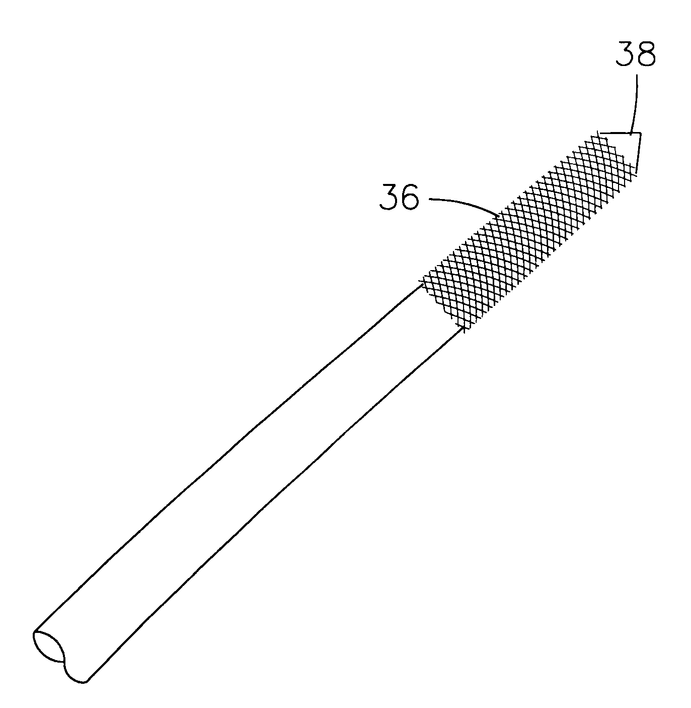
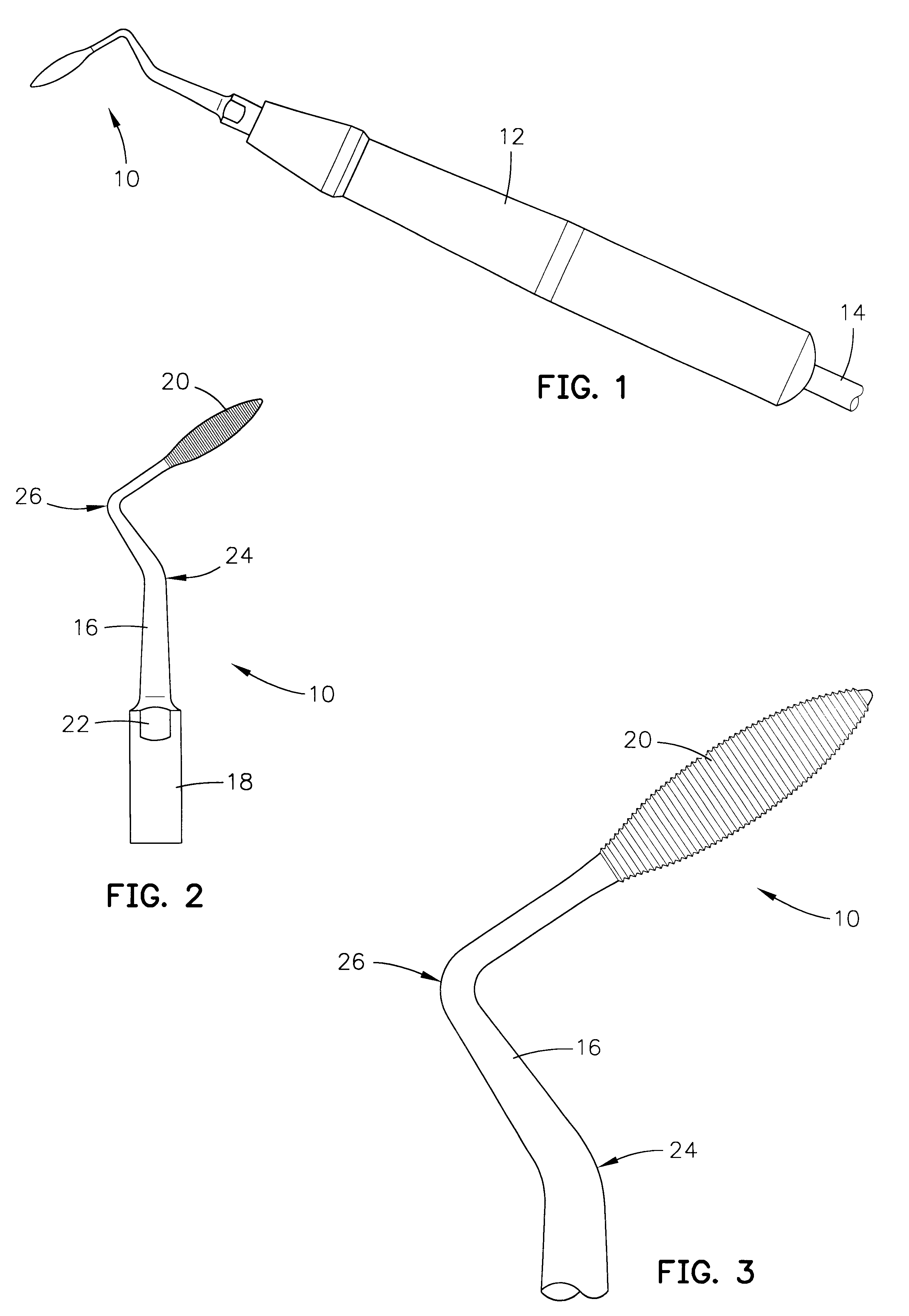
[0019]Referring to FIGS. 1 and 2 of the drawings there is illustrated an exemplary embodiment of a tool for dental surgical operations, in accordance with the present invention, designated generally by the numeral 10. The tool 10 is shown mounted in an end of an ultrasonic hand piece 12 in which is mounted an ultrasonic transducer which generates ultrasonic vibrations transmitted to the tool. The ultrasonic transducer or motor mounted in the hand piece is connected by a conductor within a line 14 to a converter box (not shown). The line 14 may also contain a water line or tube for conveying ...


PUM


Abstract

A dental tool for use with an ultrasonic transducer, includes an elongated unitary shaft member having a longitudinal axis, a proximal end and a distal end having an outer surface, an attachment member at the proximal end to enable detachable attachment to an ultrasonic transducer; and a cutting surface defined by a plurality of grooves on the outer surface forming sharp edges.

Description

FIELD OF THE INVENTION[0001]This invention relates generally to ultrasonic dental tools and pertains more particularly to special ultrasonic dental tools for periodontal disease.BACKGROUND[0002]In the past decade, ultrasonic dental tools have come into greater use and have begun to replace most rotary power and hand dental tools for drilling, cutting, shaping, cleaning and polishing teeth. Most of the powered prior art dental tools were powered by rotating electric or air motors. The tools useable with these power units were limited to rotating drills, cutters and grinders. The ultrasonic powered dental tools of recent years have several advantages over the prior art devices for most applications. Among the advantages are that they are smaller and lighter in weight and can be more easily manipulated in and around dental structures in the oral cavity.[0003]The ultrasonic power units have an entirely different type of motion than the rotary motion of air and electric motor powered uni...

Claims


Application Information

Patent Timeline
IPC IPC(8): A61C3/03A61C3/02
CPCA61C3/03
Inventor HICKOK, TERESA R.
Owner SAN DIEGO SWISS MACHINING
Why Eureka
Try Eureka