Combination tool

a technology of combinator and tool, which is applied in the field of combinator tools, can solve the problems of bulky rasps configured for cutting the edges of panels, awkward cutting and resurfacing tasks, and inconvenient use of rasps

Active Publication Date: 2011-11-08
MASSARO DANIEL J
View PDF16 Cites 23 Cited by
  • Summary
  • Abstract
  • Description
  • Claims
  • Application Information

AI Technical Summary

Problems solved by technology

The skilled tasks of cutting to size and then the resurfacing of the edges remain awkward because of the need to handle multiple tools to perform this task.
In contrast, rasps configured for cutting the edges of panels are bulky in that they are separate tools with a flat cutting surfaces that includes an extended handle or are U-shaped with a channel that has a width suitable for the positioning of the edge of the panel.
Rasps are also limited in that they typically only cut in a single longitudinal direction.
It is not uncommon, however, that the fastener is accidentally imbedded into the panel without being connected to a stud or the threads of the fastener no longer engage the panel.
The use of a large flat bladed claw hammer commonly found in construction operations to extract the fastener under these circumstances causes excessive damage to the panel.

Method used


Image

  • Combination tool
  • Combination tool
  • Combination tool

Examples


Embodiment Construction

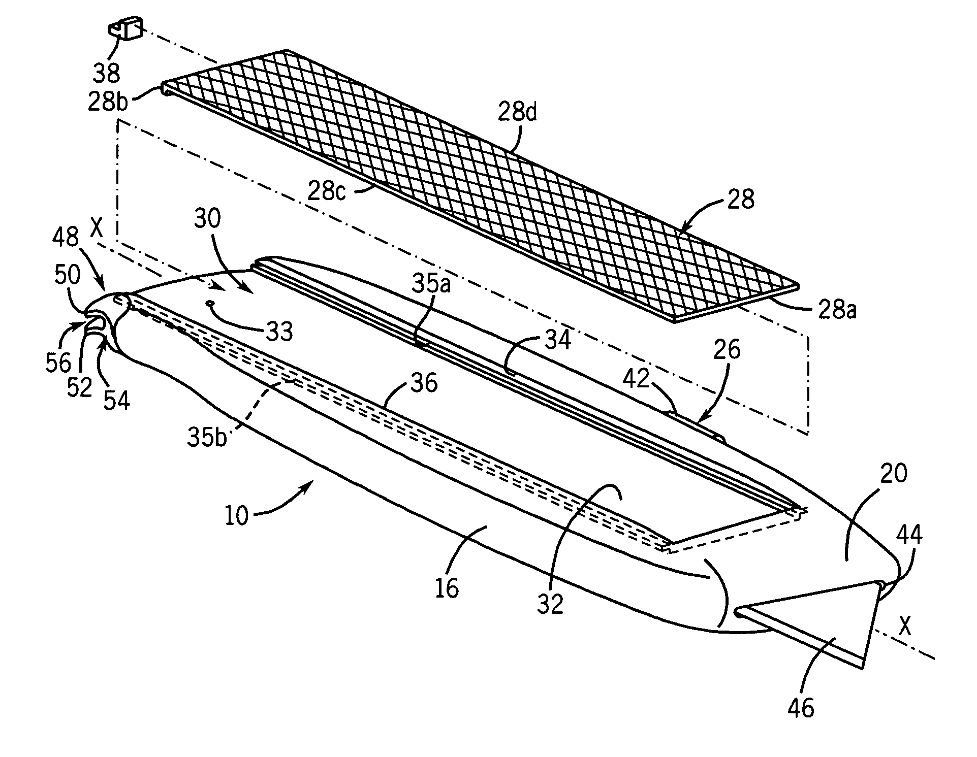
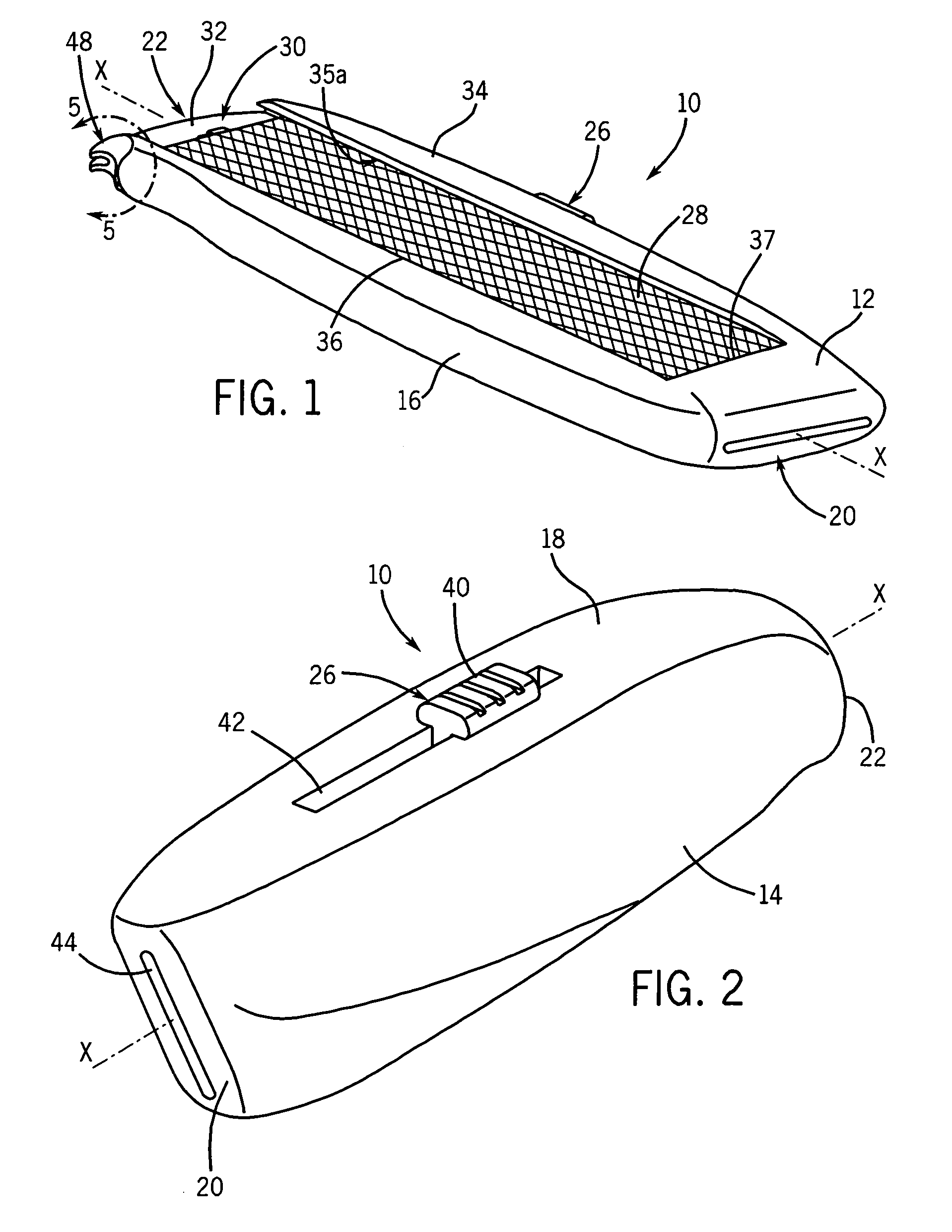
[0032]Referring initially to FIGS. 1 and 2, combination tool 10 includes an elongate housing that is a handle for a plurality of tools. The housing includes a first side 12, a second side 14, a third side 16 and a fourth side 18. First side 12 and second side 14 are opposed and have a first width. Third side 16 and fourth side 18 are opposed and have a second width that is preferably less than the first width. The housing also includes a first end portion 20 that is opposed to a second end portion 22. A central longitudinal axis-X extends along the elongate centerline of the housing through first end portion 20 and second end portion 22.

[0033]The housing preferably has an approximately rectangular cross-section that is ergonomically shaped for gripping with a single hand. Sides 12 and 14 are connected together on their longitudinally aligned sides by sides 16 and 18 to define the four elongate corners of the housing. First end portion 20 and second end portion 22 are tapered. Combin...


PUM

PropertyMeasurementUnit
anglesaaaaaaaaaa
anglesaaaaaaaaaa
anglesaaaaaaaaaa

Abstract

A combination tool is described that has a housing that includes a first side and an opposed second side, a third side and an opposed fourth side. The sides connect together to define the housing. The housing includes a first end portion and an opposed second end portion that define a longitudinal axis. The combination tool includes a razor mechanism that is connected to the housing. The razor mechanism receives and moves a cutting blade between a first position in the cavity and a second position wherein the cutting blade extends through the housing. The housing defines a channel that includes a floor, a first sidewall and a second sidewall. The first sidewall and the second sidewall have first edges that are connected to the floor and second edges that connect to the first side of the housing. The first sidewall includes a first slot and the second sidewall includes an opposed second slot. The first slot and second slot are positioned in fixed spaced relation from the floor and the second edge. The slots are configured to receive a rasp. The slots are positioned to recess a cutting surface of the rasp in the channel such that at least a portion of the sidewalls extend between the cutting surface and the second edges. A claw is defined in the housing that includes a first tong and a second tong. The claw extracts fasteners from soft materials.

Description

BACKGROUND OF THE INVENTION[0001]1. Field of the Invention[0002]The present disclosure relates to combination tools used in construction and in particular, to a combination tool that aids in the installation of panels.[0003]2. Description of the Related Art[0004]Combination tools are multi-purpose devices that can be specialized or encompass a broad range of applications. Construction and remodeling often requires the installation of panels or sheeting such as wallboard, cellulose based sheeting, polymers and insulation panels. The installation of paneling requires repetitive tasks such cutting the panel such as a piece of wallboard to the desired dimensions, resurfacing the cut edges for a smooth tight fitting joint, installing and joining the pieces of wallboard together. The resurfacing of the cut edge of the piece of wallboard is required because of the rough surface of the edges after a piece of wallboard is cut and the need for a precision uniform mating surface for any edge i...

Claims


Application Information

Patent Timeline
Patent Type & Authority Patents(United States)
IPC IPC(8): B26B11/00
CPCB26B5/001B26B11/00Y10T407/1825Y10T83/04
Inventor MASSARO, DANIEL J.
Owner MASSARO DANIEL J
Why Eureka
Try Eureka