Surgical tools and methods for their use

a technology of surgical tools and methods, applied in the field of soft tissue augmentation and reconstruction of the female breast, can solve the problems of difficult to penetrate the skin again through the exact same exit pin, significant failure and complication rate, and large morbidity

Inactive Publication Date: 2015-01-29
KHOURI ROGER
View PDF13 Cites 26 Cited by
  • Summary
  • Abstract
  • Description
  • Claims
  • Application Information

AI Technical Summary

Benefits of technology

[0001]The inventor has conceived of, reduced to practice, and patented, many inventions related to the augmentation of soft tissue including especially the augmentation and reconstruction of the female breast. Several examples of his patented inventions include the following: U.S. Pat. Nos. 5,536,233; 5,662,583; 5,676,634; 5,695,445; 5,701,917; 6,083,912; 6,478,656; 6,500,112; 6,641,527; 6,699,176; and most recently U.S. Pat. No. 8,066,691, along with other patent applications under prosecution such as 20080167613, 20100137841, and 20100160900, the disclosures of all the foregoing being incorporated herein by reference. As his investigative work has continued, he has continued to invent tools and methods for their use which enable him to implement new surgical procedures which provide strikingly improved results for his patients over existing practices and procedures implemented by other surgeons in this field. Many of these may be implemented together and thus provide the basis for them to be provided in a kit, either single use or for repeated use with one or more patients. Similarly, several of these may be implemented not only together but also in conjunction with the tools and methods of his earlier work as exemplified in his patent filings mentioned above. Furthermore, several of inventions disclosed herein, while implemented by the inventor and having been found to work, have alternate constructions or embodiments that the inventor has conceived of and which are contemplated to also work and may even be more desirable for commercialization. These tools and appliances may be briefly summarized as follows.

Problems solved by technology

Unfortunately, the TRAM flap is a major surgical procedure that carries a substantial amount of morbidity, inflicts multiple incisions and has a significant failure and complication rate.
With this process, as dictated by the typical prior art needle, it is difficult to penetrate the skin again back through the exact same exit pin hole, and even if it does, it is even more difficult to follow the exact same path along the subdermal fibers.
As a result, the thread that follows will inevitably grab some skin or some subdermal fibers along its in and out looping path, and when tightened, the stitch will almost invariably create some dimpling of the skin at each entry / exit site.
Otherwise, instead of resulting in an even line fold, the purse-string tightening may result in unsightly curtain like dimples, bulges and folds.
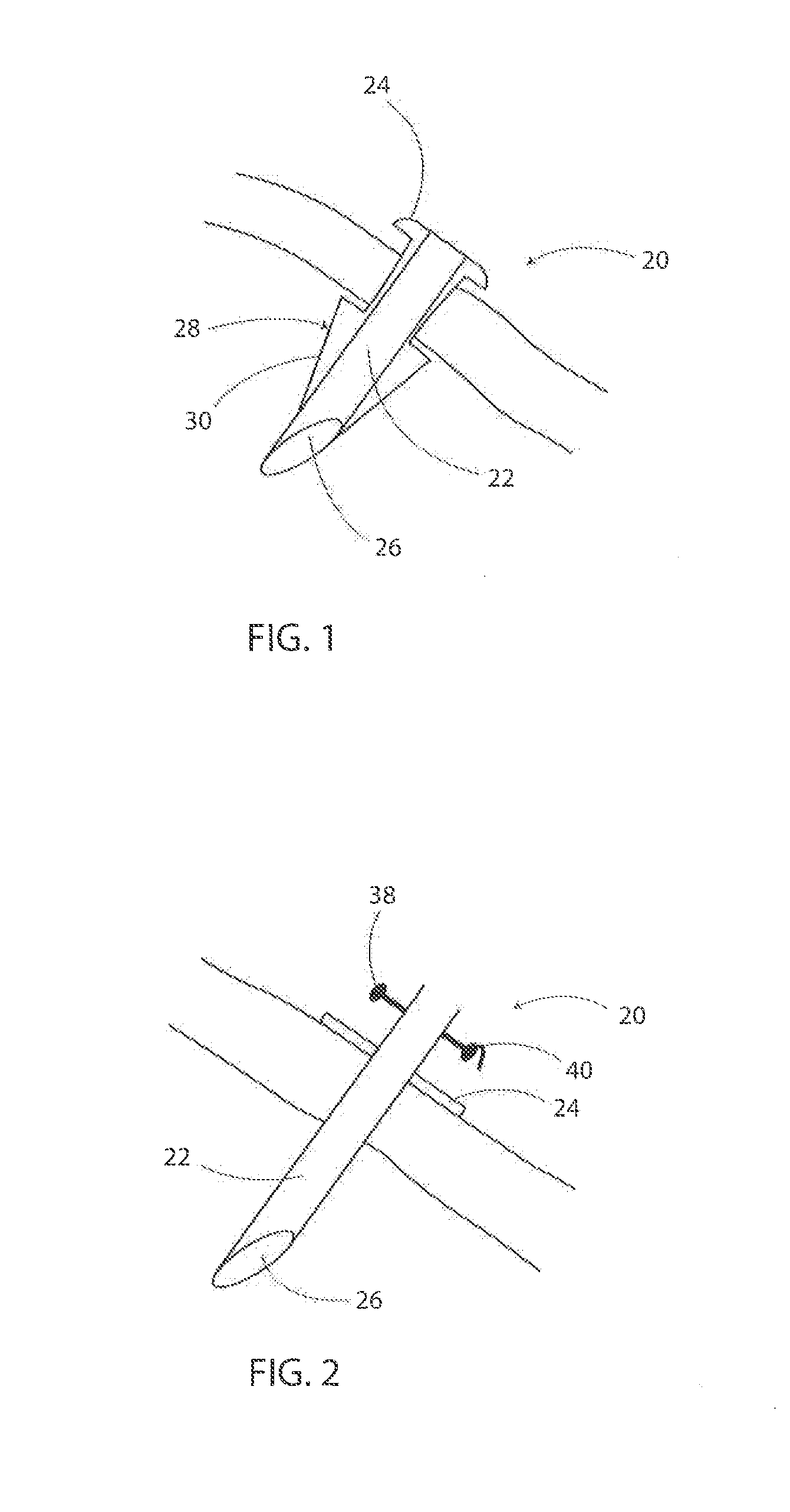
This mechanically weakens the needle at its very center where the torque is strongest while it is driven through the patient, making it prone to breaking with a broken piece deeply lodged and causing complications.
This is delicate and trickier than it may seem, as inadvertent minimal exiting of the second needle tip will inevitably catch dermal fibers during re-entry, annul the advantage of the double pointed needle and lead to failure of that entire needle path.
The problem becomes even more delicate when the desired depth / level of tissue suturing is more superficial or needs to be precisely set.
However, this may be found to be cumbersome and not ideal.
Adjusting the tightness of the suspension and of the purse string by tying a knot is not precise and the secured knot leaves behind an undesirable mass of palpable bulky tissue.
For the breast surgery procedures described infra, pulling up the abdominal tissue to the chest is limited by the resultant tightness of the advanced tissues.
Trauma, surgery, inflammation or radiation leads to tissue scarring, deficiency and stiffness that can cause disfiguring body deformities, organ dysfunction, motion restriction, pain or unstable non-healing wounds.
First, the large gap created when the released tissue is advanced leaves behind a void or a cavity that needs to be filled in order to properly heal. This void is usually filled with a flap of tissue; a step that often requires another major surgical intervention whereby vascularized tissue taken from another location on the patient's body is transferred to fill that gap.
Second, the surgical incision itself to release the tissue leaves new permanent scars. The same is true for the site where the flap is excised. This amounts to treating a scar with a scar inducing procedure.
Third, this alternative does not address the stiff fibrous scar; it only incises it and divides it in half so that the bulk of the scar tissue remains in its present state.
Fourth, the degree of advancement that can be achieved with a single incision is limited.
Fifth, by also dividing the endogenous blood vessels, the incision impairs the circulation and limits the amount of advancement.
Attempts at excising the scar are also often futile.
Simply excising the block wall in itself induces tissue trauma that often heals by leaving behind a new scar and often re-erects a new wall and does nothing to address the scar tissue deficiency problem.
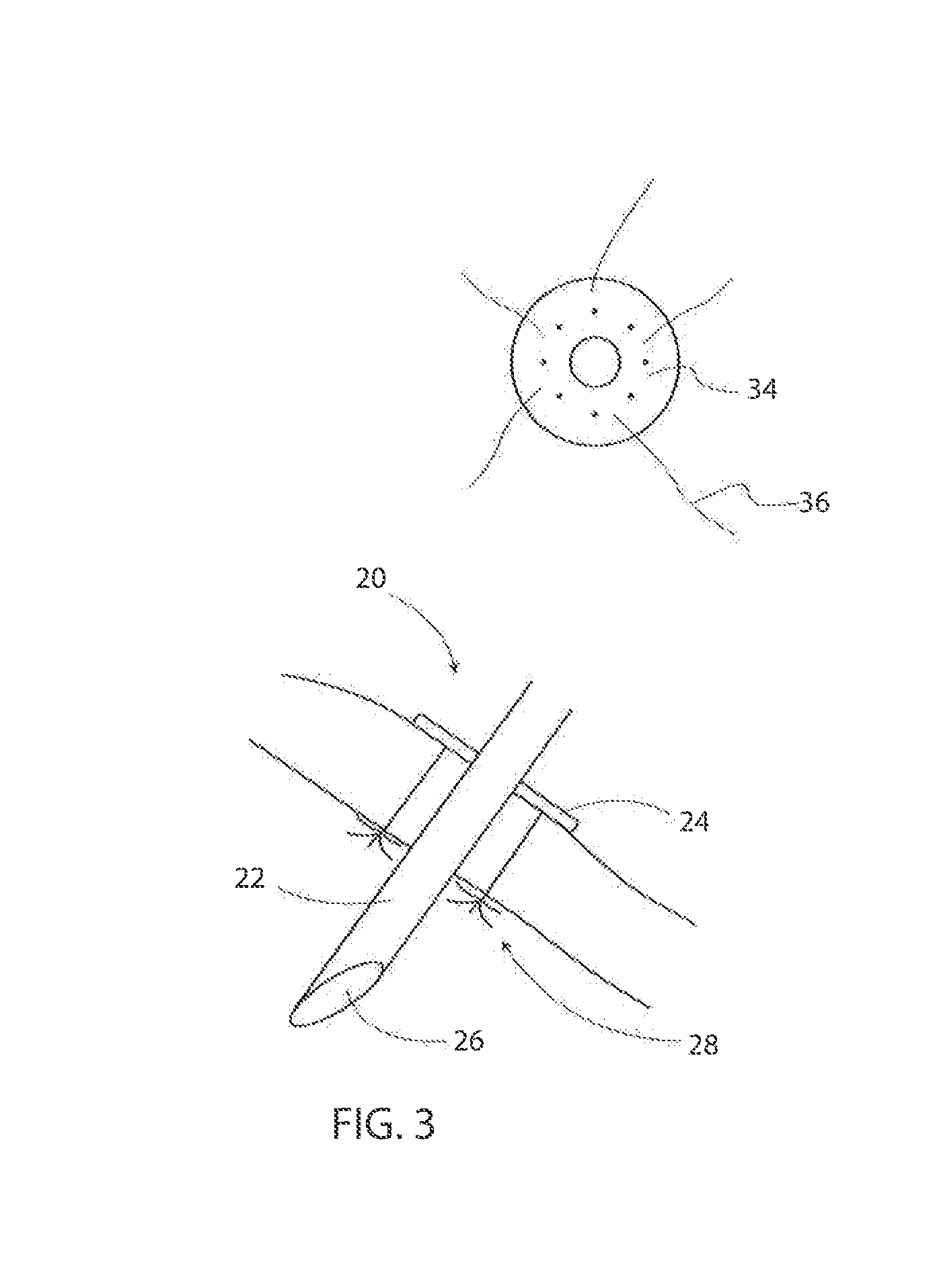
If we forcefully tighten one of the strings and keep the other loose, a needle nick to this construct will cause the tight one to snap but will leave the loose one relatively unaffected.
There is a natural limit to how much tissue can normally be advanced in order to close a wound defect, release a tight contracture or create a breast mound.
Trying to advance the skin beyond the natural laxity limit of this subcutaneous aponeurosis places these structures under tension rendering them much more susceptible to being nicked by a needle tip and thus separated than the surrounding tissues.
Too aggressive a meshing will destroy the circulation, leading to ischemia and necrosis.
It can also tear the deeper tissues and result in the creation of excessively large cavities instead of those of a delicate fibrovascular recipient scaffold.
Excessive meshing destroys the integrity of the scaffold and leads to excessive numbers or sizes of cavities.
The current practical limitation of tissue engineering is not the cells, as these are readily available from simple liposuction or from tissue cultures, but the three dimensional supporting scaffold with functional blood capillaries connected to the circulation of the recipient.
It is the inability in the prior art to build a fibrovascular scaffold (fibrous scaffold with capillary circulation) in the laboratory and connect it to the recipient blood circulation that limits the ability to build three dimensional solid organs or blocks of tissue.
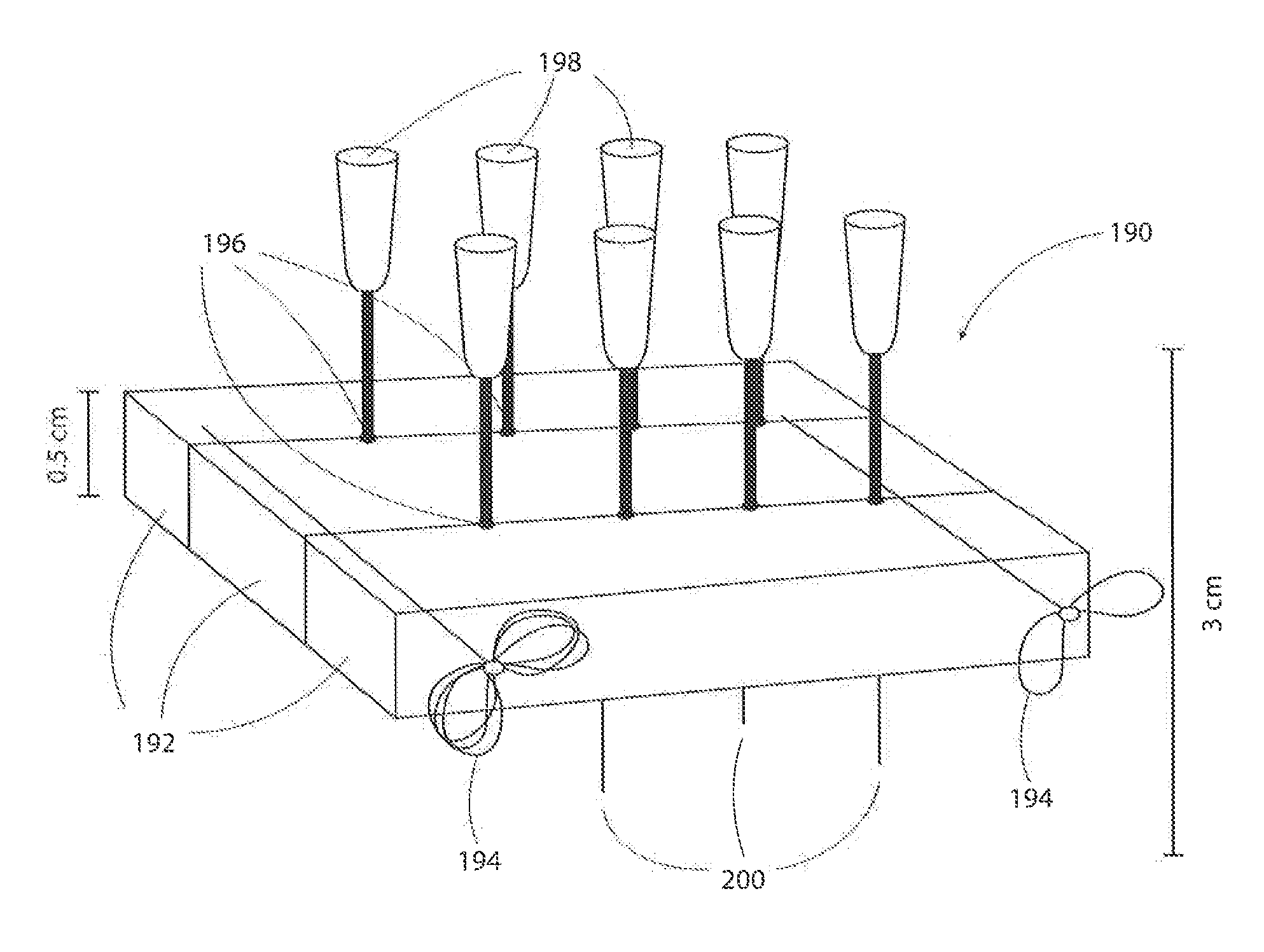
The inventor contemplates that thinner rods will not have enough mechanical torsional strength to do most jobs and thicker ones will leave more noticeable scars at the entrance points.
Unfortunately, these devices have limited effectiveness; proof is that despite years on the market, they have not replaced the surgical facelift operation.
The effectiveness of these devices is limited by their inability to safely deliver the amount of injury to the deep dermis and subcutaneous tissue that will result in the required scar retraction while completely sparing the more superficial delicate tissues from the injurious agent.
Since the distance between these two tissue layers is of the order of millimeters and fractions of millimeters, even a limited scatter of the most precisely focused agent is bound to cause collateral damage.
This tailoring operation requires multiple incisions to remove (or plicate) the excess skin and therefore leaves behind unsightly scars.
The main problem in breast ptosis is the excess skin and laxity of the internal suspensory ligament (also called ligament of Cooper).
If the brassiere is not adherent or not stiff, some threads might be tightened more than others to cause unsightly dimples.

Method used


Image

  • Surgical tools and methods for their use
  • Surgical tools and methods for their use
  • Surgical tools and methods for their use

Examples


Embodiment Construction

[0152]As shown in FIG. 1-3, a grommet 20 includes a central, cylindrical shaft 22 preferably with a top hat, annular flange 24 for engaging the skin surface as it is inserted into an incision in the patient's skin. The cylindrical shaft 22 preferably has a beveled tip 26 to aid in its insertion and which provides directionality for locating and threading therethrough a needle and thread, as is explained in greater detail below. Various embodiments of a stop 28 are depicted, as follows. As shown in FIG. 1, a collapsible pair of wings 30 may extend from the sidewall of the shaft 22, and which open to block unintended removal or exiting of the grommet 20 during use but which may be collapsed to facilitate its removal, when desired. Two other embodiments of a stop 28 are depicted in FIG. 4 and include a collapsible umbrella 32 extending from the flange 24. Or, as yet another alternative, the flange 24 may be provided with a series of holes 34 through which a suture, pin or other structu...


PUM


Abstract

Surgical tools and kits for performing methods include a grommet with cylindrical shaft, cutting tip, annular flange with suture retaining anchoring fixture; a grommet jig for extending between adjacent grommets and guiding a needle therebetween; a family of needles with single and double pointed ends, reinforced eyelets, stops to limit inadvertent exiting, double shaft construction with a longitudinal gap and sharpened, slicing ends, including a “J” shape embodiment; a bone anchor with ring to secure sutures about a patient's clavicle; a tissue dissector having radially extending cones to nick taut connecting tissues; a tissue rasp having a series of crisscrossing grooves along an end; a tissue mesher comprising one or more blocks having a matrix of holes for clamping a plurality of needles and a supporting framework; and a kit device and a method of surgically inserting an internal mesh brassiere under the breast skin.

Description

BACKGROUND AND SUMMARY OF THE INVENTION[0001]The inventor has conceived of, reduced to practice, and patented, many inventions related to the augmentation of soft tissue including especially the augmentation and reconstruction of the female breast. Several examples of his patented inventions include the following: U.S. Pat. Nos. 5,536,233; 5,662,583; 5,676,634; 5,695,445; 5,701,917; 6,083,912; 6,478,656; 6,500,112; 6,641,527; 6,699,176; and most recently U.S. Pat. No. 8,066,691, along with other patent applications under prosecution such as 20080167613, 20100137841, and 20100160900, the disclosures of all the foregoing being incorporated herein by reference. As his investigative work has continued, he has continued to invent tools and methods for their use which enable him to implement new surgical procedures which provide strikingly improved results for his patients over existing practices and procedures implemented by other surgeons in this field. Many of these may be implemented ...

Claims


Application Information

Patent Timeline
Patent Type & Authority Applications(United States)
IPC IPC(8): A61B17/3205A61B17/34
CPCA61B17/3494A61B17/32053A61F13/14A61B17/0401A61B17/0482A61B17/06066A61B2017/00792A61B2017/00796A61B2017/0414A61B2017/044A61B2017/06042A61B2017/06047A61B2017/06071A61B2017/0608A61B2017/0609A61B17/205A61B2017/3225A61B90/02A61F2250/0067A61B17/3417A61B2017/0023A61B2017/3454A61F2/12A61K35/16
Inventor KHOURI, ROGER
Owner KHOURI ROGER
Why Eureka
Try Eureka