Method for building sets of mobile stations in MIMO systems, corresponding mobile station, base station, operation and maintenance centre and radio communication network

a technology of mobile stations and mimo systems, applied in the field of building sets of mobile stations in radio communication networks, can solve the problems of consuming a considerable amount of the maximum uplink capacity of a radio cell, and reducing considerably the overhead, so as to reduce the overhead. the effect of reducing the overhead

Inactive Publication Date: 2011-07-07
ALCATEL LUCENT SAS
View PDF15 Cites 49 Cited by
  • Summary
  • Abstract
  • Description
  • Claims
  • Application Information

AI Technical Summary

Benefits of technology

[0017]The first feedback information and the second feedback information comprise information only about one of the downlink beams. Reporting only this information reduces considerably a reporting overhead in comparison to a case, where channel quality indications for all downlink beams are reported and therewith a considerable amount of a maximum uplink capacity of a radio cell is consumed.
[0018]For example using a 3 bit codebook with 8 allowed precoding vectors, reporting only the channel quality of the downlink beam with the largest received carrier power reduces the overhead by a factor of 8 in comparison to the case where channel quality information for all downlink beams is reported.

Problems solved by technology

Reporting only this information reduces considerably a reporting overhead in comparison to a case, where channel quality indications for all downlink beams are reported and therewith a considerable amount of a maximum uplink capacity of a radio cell is consumed.

Method used


Image

  • Method for building sets of mobile stations in MIMO systems, corresponding mobile station, base station, operation and maintenance centre and radio communication network
  • Method for building sets of mobile stations in MIMO systems, corresponding mobile station, base station, operation and maintenance centre and radio communication network
  • Method for building sets of mobile stations in MIMO systems, corresponding mobile station, base station, operation and maintenance centre and radio communication network

Examples


first embodiment

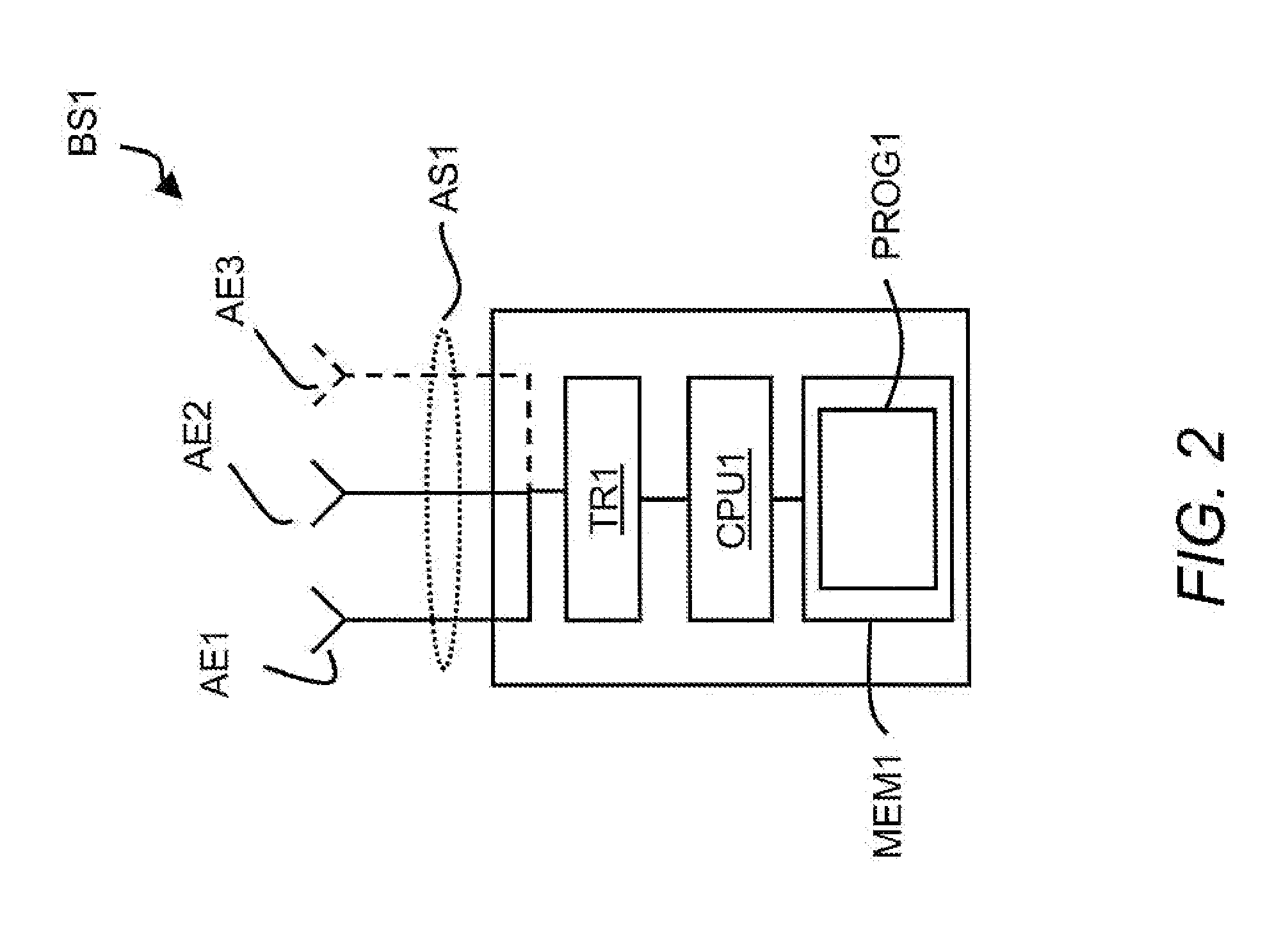
[0045]The first computer readable program PROG1 is foreseen for executing steps of the method according to the invention. The first CPU CPU1 is foreseen for executing the first computer readable program PROG1.

[0046]Referring to FIG. 3 the first mobile station MS1 of FIG. 1 contains a second antenna system AS2, a second transceiver TR2, a second CPU CPU2, and a second computer readable medium MEM2.

[0047]The second antenna system AS2 contains a fourth antenna element AE4 and a fifth antenna element AE5. The second antenna system AS2 can also contain more than two antenna elements for reception and / or transmission. But this is not shown for simplification.

[0048]The fourth antenna element AE4 and the fifth antenna element AE5 are used for the first downlink channel DL1 and the first uplink channel UL1. Alternatively a further antenna element can be used to split downlink and uplink transmission on different antenna elements.

[0049]The second transceiver TR2 receives the first reference s...

second embodiment

[0092]FIG. 7 shows a method M2 for use in the first radio communication system RCS1. The method M2 will be used as an improvement according to the invention, if a parameter describing the angular beam spread is below a first threshold value of within a first range of values. The angular beam spread depends on the inter-beam interference of the downlink beams DB1, DB2, DB3, and DB4. The parameter can be derived for example from the CQI values reported by the mobile stations MS1, MS2, and MS3.

[0093]The steps shown in FIG. 7 that correspond to the steps of the FIG. 5 have been designated by same reference numerals. In addition to the steps M1 / 1, M1 / 2, M1 / 3, M1 / 4, M1 / 5, M1 / 6, M1 / 7, M1 / 8, and M1 / 9 performed in the first embodiment of the invention, in the second embodiment of the invention following step M2 / 1 is performed after the step M1 / 8 and either the step M1 / 9 or step M2 / 2 is performed after the step M2 / 1.

[0094]In the further step M2 / 1 the first base station BS1 compares the parame...

third embodiment

[0099]It is a further improvement according to the invention to adapt a selection of transport formats for the mobile stations of the mobile station set according to the use of the minimum beam distance method. Such adaptation should account for a transmit power split to multiple downlink beams.

[0100]FIG. 8 shows a method M3 for use in the first radio communication system RCS1 according to the third embodiment of the invention. The elements shown in FIG. 8 that correspond to elements of the FIG. 7 have been designated by same reference numerals.

[0101]In addition to the steps M1 / 1, M1 / 2, M1 / 3, M1 / 4, M1 / 5, M1 / 6, M1 / 7, M1 / 8, M1 / 9, M2 / 1, and M2 / 2 of the method M2 following step M3 / 1 is performed after the step M2 / 2.

[0102]In the further step M3 / 1, the first base station BS1 selects a transport format for each mobile station of the mobile station set according to the reported CQI values and according to a PSF parameter (PSF=power split factor). The PSF parameter is used because multiple d...


PUM


Abstract

The invention relates to a method for building sets of mobile stations in a radio communication network (RCS1), wherein the method comprising the steps of: transmitting (M1/1) reference signals from a base station (BS1) to at least two mobile stations (MS1, MS2, MS3) for being able to determine channel properties of a downlink channel (DL1) between the base station (BS1) and the at least two mobile stations (MS1, MS2, MS3); determining (M1/3, M1/4, M1/5, M1/6) a first feedback information at a first one of the at least two mobile stations (MS1, MS2, MS3) and a second feedback information at a second one of the at least two mobile stations (MS1, MS2, MS3) each comprising a first component indicating a channel quality; transmitting (M1/7) the first and the second feedback information from the first one and the second one of the at least two mobile stations (MS1, MS2, MS3) to the base station (BS1); and building (M1/9) a mobile station set according to the first and the second feedback information at the base station (BS1), wherein the channel quality is a parameter of a downlink beam with a largest received carrier power of at least three downlink beams (DB1, DB2, DB3, DB4) of said downlink channel (DL1).

Description

[0001]This application is a U.S. national filing of PCT / EP2009 / 059462 which is based on a priority application EP 08 305 575.6, both of which are hereby incorporated by reference.FIELD OF THE INVENTION[0002]The invention relates to a method for building sets of mobile stations in a radio communication network, said method comprising the steps of:transmitting reference signals from a base station for being able to determine channel properties of a downlink channel between said base station and at least two mobile stations; receiving said reference signals by said at least two mobile stations; determining a first feedback information at a first one of said at least two mobile stations and a second feedback information at a second one of said at least two mobile stations comprising each a first component indicating a channel quality of a downlink beam with a largest received carrier power of at least three downlink beams of said downlink channel and a second component indicating said d...

Claims


Application Information

Patent Timeline
Patent Type & Authority Applications(United States)
IPC IPC(8): H04B17/00
CPCH04B7/0619H04B7/0632H04W72/085H04B7/0695H04W16/24H04B7/066H04B7/0452H04W72/542H04B7/0617H04W24/04H04W72/121
Inventor HOEK, CORNELISWILD, THORSTEN
Owner ALCATEL LUCENT SAS
Why Eureka
Try Eureka