
Grain cart with directional discharge

a technology of grain carts and directional discharges, applied in the field of carts and systems for handling grains, can solve the problems of inability to use on the fly, difficult to move from side to side,

Inactive Publication Date: 2011-07-07
HOLLENBERG DAVID H
View PDF24 Cites 23 Cited by
  • Summary
  • Abstract
  • Description
  • Claims
  • Application Information

AI Technical Summary

Benefits of technology

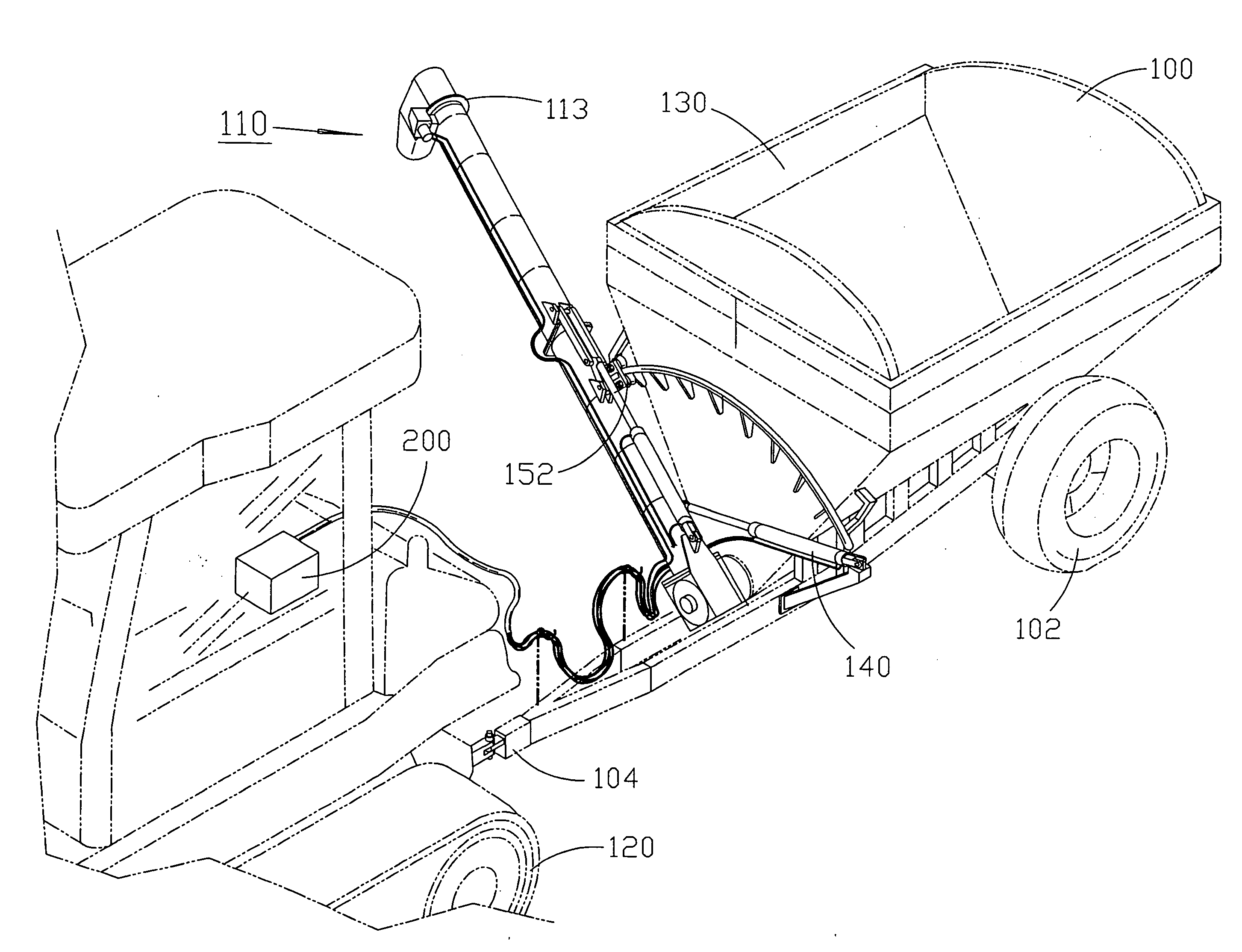
[0009]A grain cart grain discharge including a pivotable discharge chute having a first position to discharge grain from a first side of a grain cart and a second position to discharge grain from an opposite side of the cart. The discharge chute is movably mounted on a guide and pivotable about the central axis of a grain supply auger mounted at t...

Problems solved by technology

This patent discloses an auger that can be positioned to dispense from either side of the wagon but the auger takes up space in the cart and thus would be hard to move from side to side and the cart requires manual movement using the handle 38 and thus cannot be used on the fly.

Method used


Image

  • Grain cart with directional discharge
  • Grain cart with directional discharge
  • Grain cart with directional discharge

Examples


Embodiment Construction

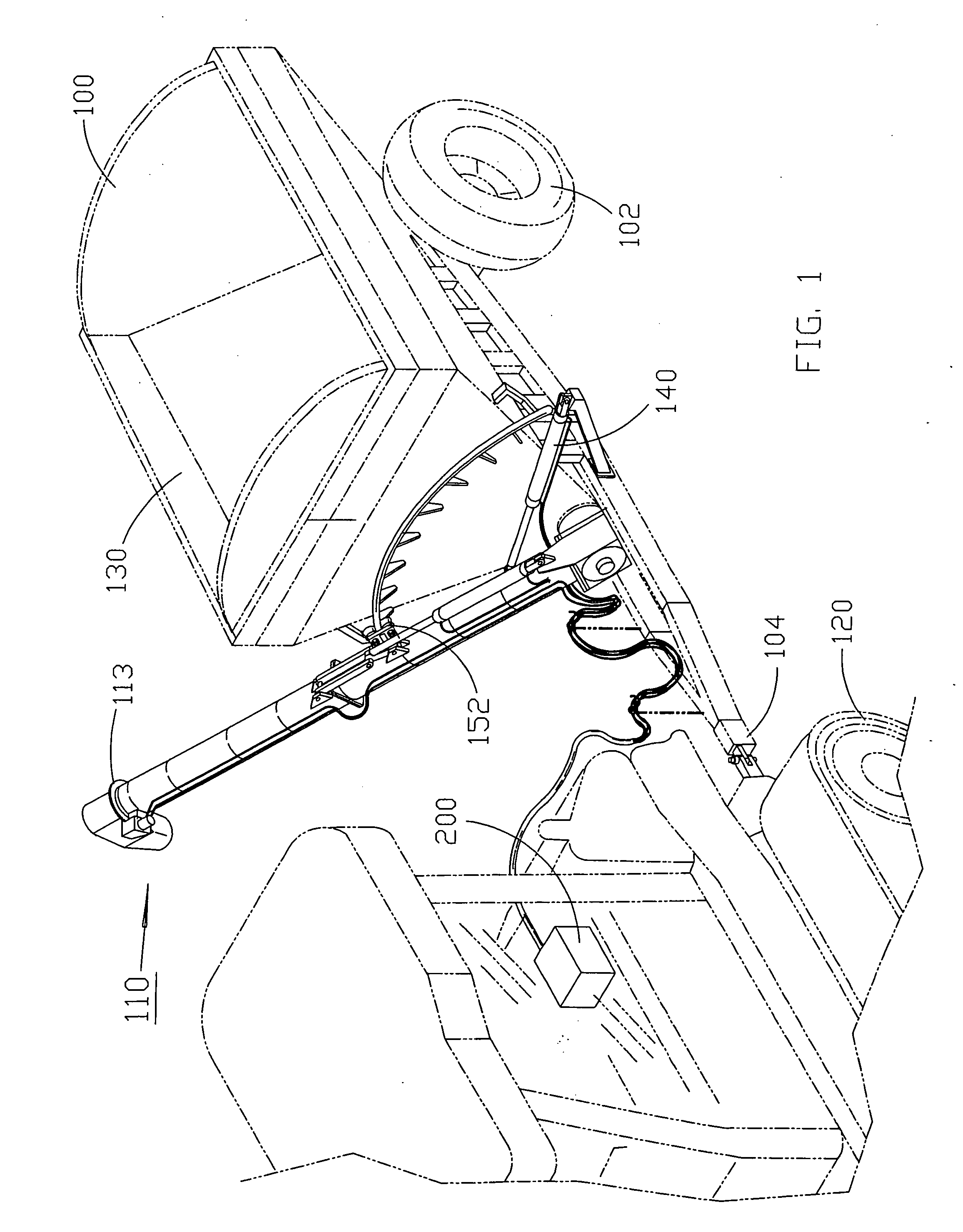
[0015]In accordance with the present invention, FIG. 1 shows a grain handling vehicle such as a grain cart 100 with a directional discharge chute 110. The grain cart 100 is pulled by a vehicle 120 such as a combine, tractor or truck, alternatively the cart could have its own power. In the case where the vehicle 120 is a combine, as the combine travels it pours grain into the hopper 130. The grain cart 100 includes a pair of tires 102 and a tongue 104. The discharge chute 110 is in communication with an auger (FIG. 3) in the base of the hopper 130. A control 200 in or on the vehicle 120 can be used to control the operation of the grain cart 100 and chute 110.

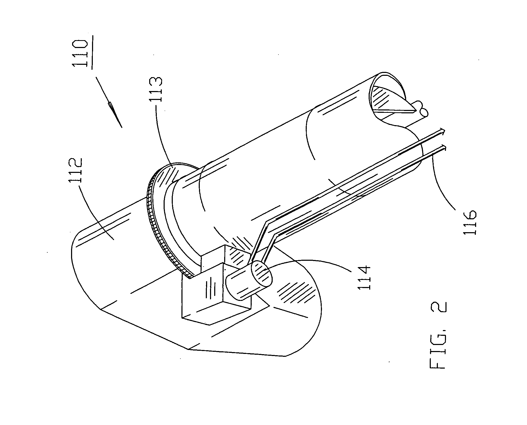
[0016]FIG. 2 shows that the discharge chute 110 includes a discharge head 112 rotationally mounted to the chute 110, the discharge head 112 can rotate 360 degrees about the center axis of the chute 110 using a means such as a gear 113 or chain drive for example. The position of the discharge head 112 is controlled by a motor 114 ...


PUM


Abstract

A grain cart grain discharge including a pivotable discharge chute having a first position to discharge grain from a first side of a grain cart and a second position to discharge grain from an opposite side of the cart. The discharge chute is movably mounted on a guide and pivotable about the central axis of a grain supply auger mounted at the bottom of a grain hopper. A discharge head rotatably located on an end of the discharge chute opposite the supply auger and a control located on a vehicle, the control controlling the movement of the chute from the first position to the second position and controlling a rotational position of the discharge head without leaving the cab of the vehicle.

Description

CROSS REFERENCES TO RELATED APPLICATIONS [0001]I hereby claim the benefit under 35 USC 119e of provisional patent application 61 / 335,357 filed Jan. 6, 2010.STATEMENT AS TO RIGHTS TO INVENTIONS MADE UNDER FEDERALLY SPONSORED RESEARCH AND DEVELOPMENT [0002]Not ApplicableBACKGROUND OF THE INVENTION[0003]1. Field of the Invention[0004]This invention relates to carts and systems for handling grain.[0005]2. Brief Description of Prior Art[0006]There is a need to handle grain.[0007]U.S. Pat. No. 4,415,303 shows a grain cart used to handle grain as it is being harvested and after. This patent discloses an auger that can be positioned to dispense from either side of the wagon but the auger takes up space in the cart and thus would be hard to move from side to side and the cart requires manual movement using the handle 38 and thus cannot be used on the fly.[0008]As will be described, the preferred embodiments of the present invention overcome disadvantages of the prior art.SUMMARY OF THE INVE...

Claims


Application Information

Patent Timeline
IPC IPC(8): B60P1/42B60P1/40
CPCB60P1/42
Inventor HOLLENBERG, DAVID H.
Owner HOLLENBERG DAVID H
Learn More