Channel laryngoscopes and systems

Active Publication Date: 2011-07-21
VERATHON MEDICAL CANADA ULC
View PDF1 Cites 57 Cited by
  • Summary
  • Abstract
  • Description
  • Claims
  • Application Information

AI Technical Summary

Problems solved by technology

It is well known that failure to intubate when required can lead to death or serious injury.
Intubation is a complex process which presents numerous challenges, as well as myriad possible injuries to the

Method used


Image

  • Channel laryngoscopes and systems
  • Channel laryngoscopes and systems
  • Channel laryngoscopes and systems

Examples


Embodiment Construction

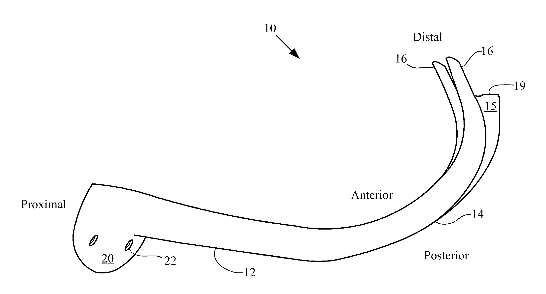
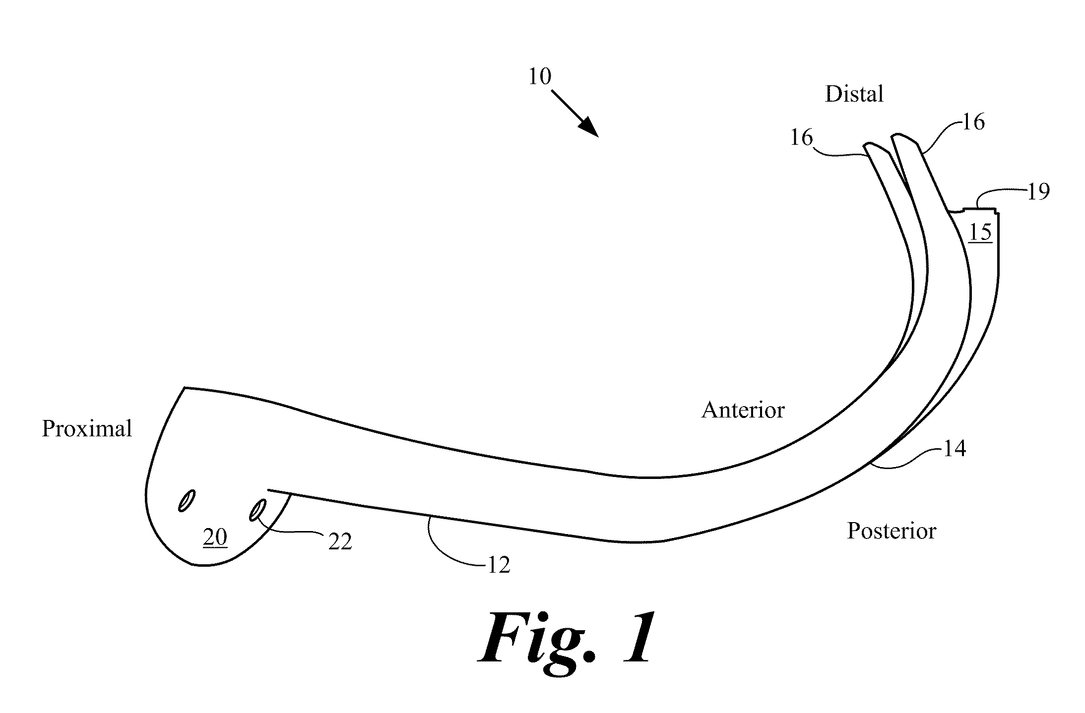
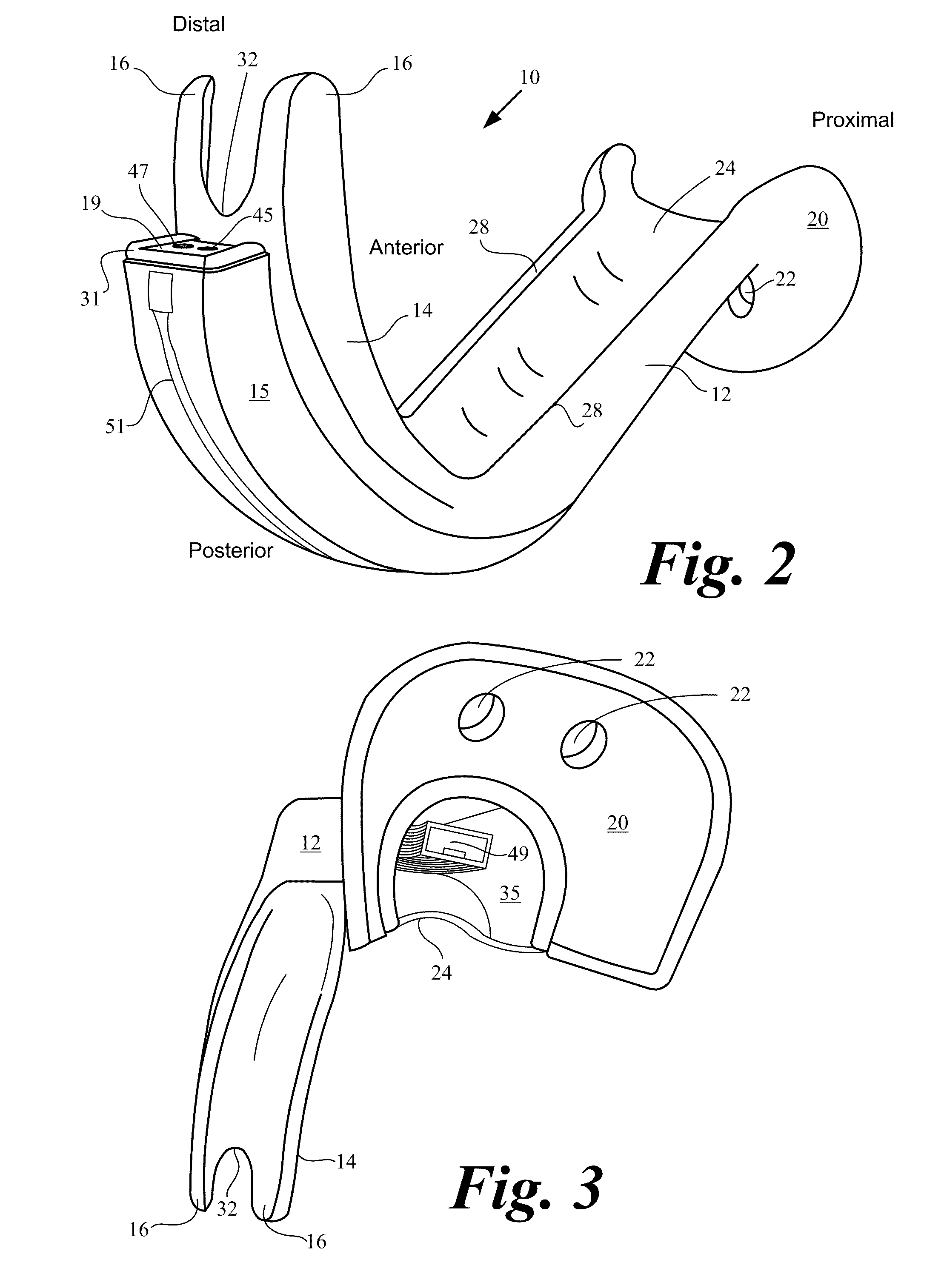
[0039]Several embodiments of a video-based intubation laryngoscope and system are described that allow for examination of the upper airway and intubation. The system employs video laryngoscope embodiments configured to hold and position an ETT for insertion into the trachea of a patient minimizing (reducing) the need for accessory stylets. Improved intubation speed and intubation accuracy is accomplished by the specific configurations in that unobstructed, real time or “live” views are immediately obtained on a viewable display monitor. The laryngoscopes configurations described herein provide an aiming aid that allows real time re-positioning of the video laryngoscope to optimally align the tip of the ETT with the glottic aperture just prior to advancing the ETT through the glottis from the video laryngoscope. The video laryngoscopes provide clear, direct images of the larynx, vocal cords, and laryngeal area on the display monitor and offer a means to control the trajectory of the ...


PUM


Abstract

Video-based laryngoscopes having an external centrally located channel coursing from the handle to a curved blade configured to deliver an ETT to a trachea as visualized by a non-removable, or alternatively, a removable video camera and lighting unit located beneath the external channel. The channel laryngoscope may be made for single use in a patient and discarded, or be processed for re-use. Alternatively, the channel laryngoscope may have a removable video camera and lighting member located within an internal chamber that runs parallel with the external channel. In another embodiment a laryngoscope adapter may be detachably affixable to the channel laryngoscope equipped with the non-removable camera to provide a decontaminated or sterile surface to permit re-use of the channel laryngoscope without having to undergo washing or decontamination procedures.

Description

CROSS REFERENCES TO RELATED APPLICATIONS[0001]This application claims priority to and the benefit of the filing date of U.S. Provisional Patent Application No. 61 / 261,739 filed Nov. 16, 2009 and U.S. Provisional Patent Application No. 61 / 319,835 filed Mar. 31, 2010, both of which are hereby incorporated by reference in their entirety.[0002]The application incorporates by reference in their entirety U.S. Pat. No. 6,142,144 filed Apr. 1, 1998 and its U.S. Provisional Patent Application Nos. 60 / 074,355 filed Feb. 10, 1998 and 60 / 067,205 filed Dec. 7, 1997; U.S. Pat. No. 6,543,447 filed Dec. 6, 2000 and its U.S. patent application Ser. Nos. 09 / 704,507 filed Nov. 2, 2007 and 09 / 060,891 filed Apr. 15, 1998; and U.S. Pat. No. 6,655,377 filed Jan. 30, 2003 and its U.S. patent application Ser. Nos. 09 / 732,129 filed Dec. 6, 2000 and 09 / 704,507 filed Nov. 2, 2000, and U.S. Provisional Patent Application Nos. 60 / 352,283 filed Jan. 30, 2002; 60 / 223,330 filed Aug. 7, 2000; 60 / 168,711 filed Dec. 6...

Claims


Application Information

Patent Timeline
IPC IPC(8): A61B1/267
CPCA61B1/267A61B1/00142
Inventor PACEY, JOHN ALLENVISSER, MITCHELLYAZDI, REZA AHMADIANKIM, YONGKOOK
Owner VERATHON MEDICAL CANADA ULC
Why Eureka
Try Eureka