Building management system with fault analysis

a technology of management system and fault analysis, applied in pulse technique, program control, instruments, etc., can solve problems such as excess number, energy consumption, and decrease in equipment lifespan

Active Publication Date: 2011-07-21
JOHNSON CONTROLS TECH CO
View PDF131 Cites 352 Cited by
  • Summary
  • Abstract
  • Description
  • Claims
  • Application Information

AI Technical Summary

Benefits of technology

The patent describes a method and system for detecting and analyzing faults in a building management system. The system uses data from various devices in the building to detect and evaluate potential faults. When a fault is detected, the system acquires and stores new data from the building management system to better understand the source of the fault. This analysis can help to identify and fix the problem causing the fault. The system can also update prior probabilities and apply Bayes' theorem to determine the most likely fault cause. The technical effects of this invention include improved fault detection and analysis, improved data logging, and improved system efficiency.

Problems solved by technology

The patent text discusses the problem of fault detection in building management systems. These systems use fault detection to alert users about equipment malfunctions, but over-sensitive fault detection can lead to too many alerts, incorrect analysis, and decreased system performance. It is challenging to develop effective fault detection strategies for these systems.

Method used


Image

  • Building management system with fault analysis
  • Building management system with fault analysis
  • Building management system with fault analysis

Examples


Embodiment Construction

The present invention relates to a building management system configured to improve building efficiency, to enable greater use of renewable energy sources, and to provide more comfortable and productive buildings.

A building management system (BMS) is, in general, hardware and / or software configured to control, monitor, and manage devices in or around a building or building area. BMS subsystems or devices can include heating, ventilation, and air conditioning (HVAC) subsystems or devices, security subsystems or devices, lighting subsystems or devices, fire alerting subsystems or devices, elevator subsystems or devices, other devices that are capable of managing building functions, or any combination thereof.

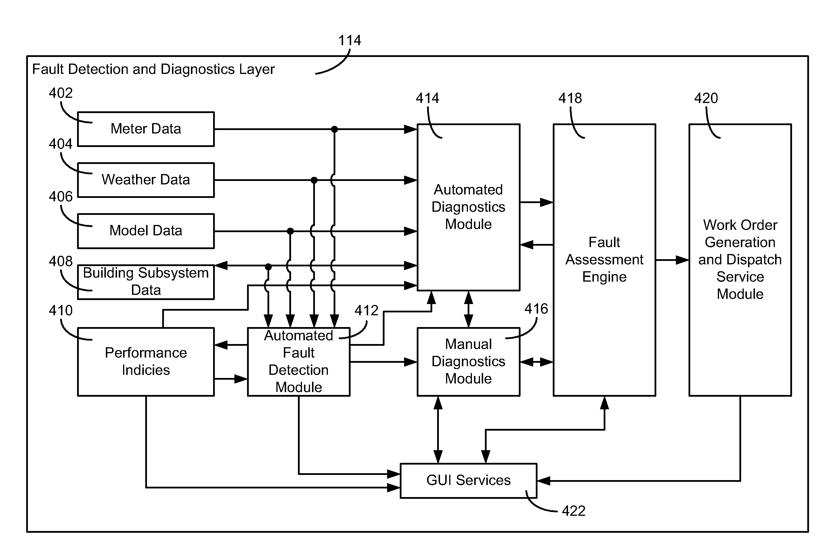
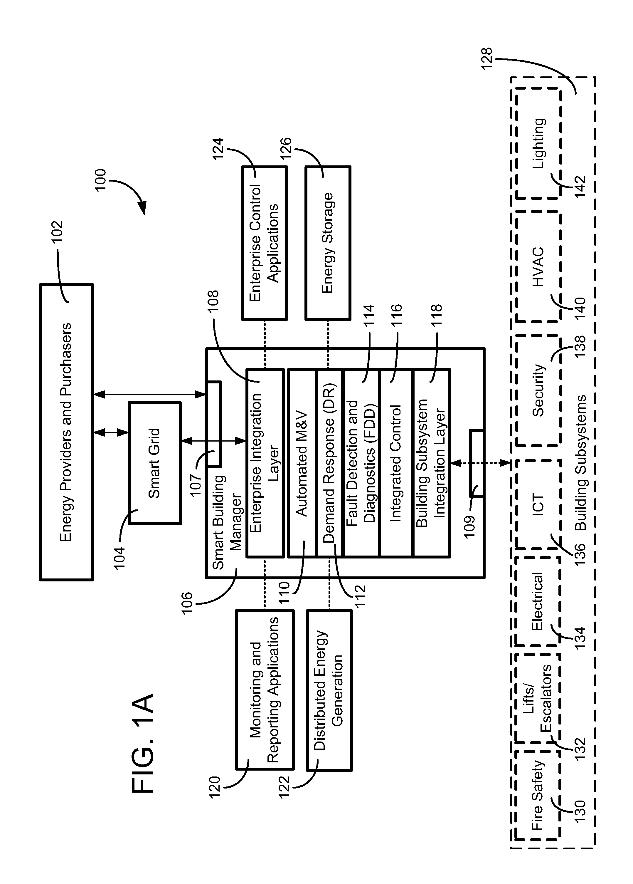
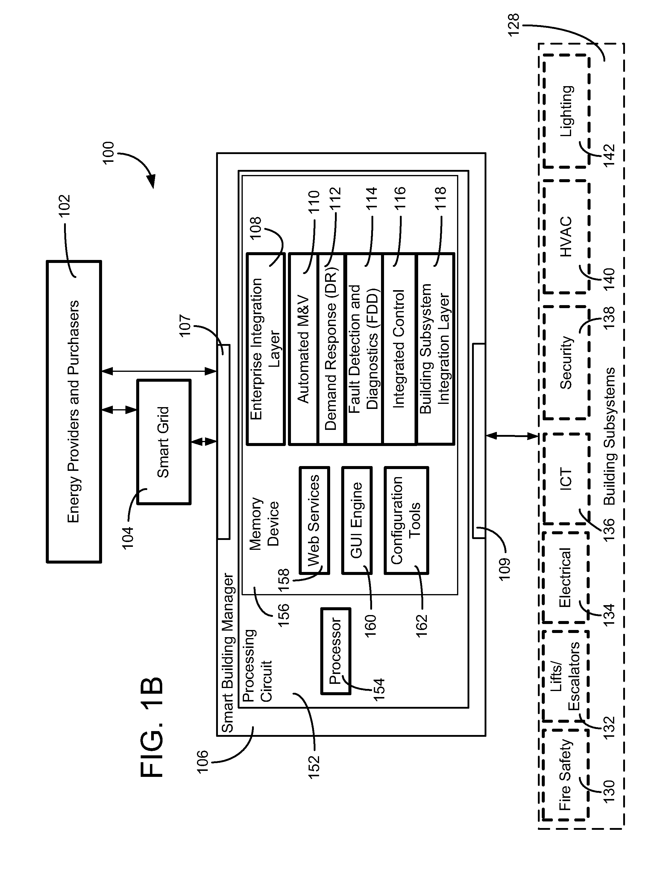
Referring now to FIG. 1A, a block diagram of a system 100 including a smart building manager 106 is shown, according to an exemplary embodiment. Smart building manager 106 is connected to a smart grid 104 and a plurality of building subsystems 128. The building subsystems 128 may ...


PUM


Abstract

A controller for a building management system is configured to analyze faults in the building management system. The controller detects a fault in the building management system by evaluating data of building management system using a system of rules. The controller determines a conditional probability for each of a plurality of possible fault causes given the detected fault. The controller determines the most likely fault cause by comparing the determined probabilities and electronically reports the most likely fault cause.

Description


Claims


Application Information

Patent Timeline
Owner JOHNSON CONTROLS TECH CO
Why Eureka
Try Eureka