

Offset Control for Assemblying an Electronic Device Housing
a technology of electronic devices and offset control, which is applied in the direction of electrical apparatus casings/cabinets/drawers, coupling device connections, instruments, etc., to achieve the effect of high degree of precision
- Summary
- Abstract
- Description
- Claims
- Application Information
AI Technical Summary
Benefits of technology
Problems solved by technology
Method used
Image

Examples
Embodiment Construction
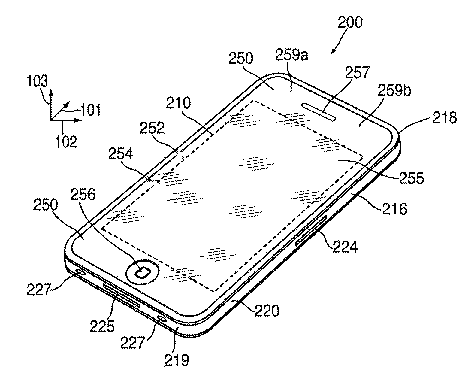
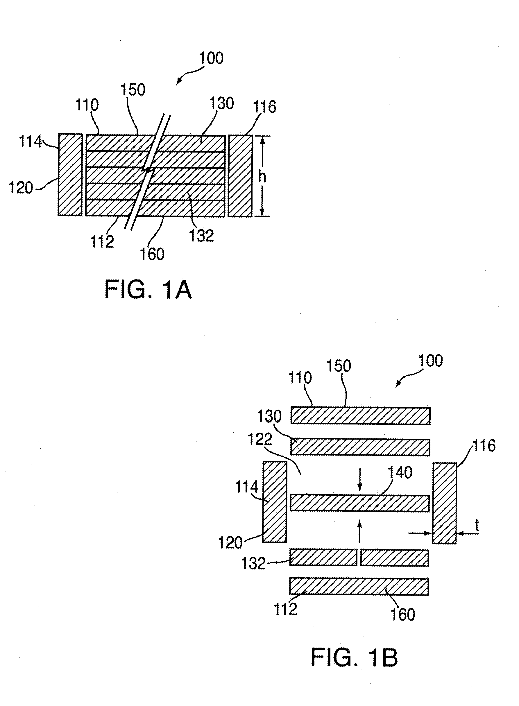
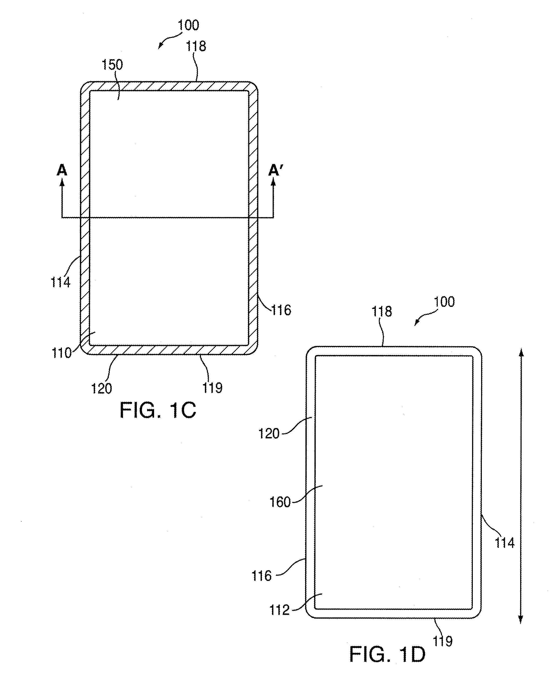
Embodiments are described herein in the context of a housing for an electronic device. The housing can make use of an outer member. The outer member can be aligned, protected and / or secured with respect to other portions of the housing for the electronic device. The electronic device can be portable and in some cases handheld.
According to one aspect, adjoining surfaces of electronic device housings can be mounted or arranged such that adjoining surfaces are flush to a high degree of precision. Edges of portable electronic devices are susceptible to impact force, such as when dropped. According to another aspect, protective sides can be provided on edges of electronic device housings so to dissipate impact forces and thus reduce damage to electronic device housings. According to still another embodiment, an electronic device housing can have one or more of its exposed major surfaces (e.g., front or back surfaces) formed of glass. The glass surfaces can be protected by the protective ...
PUM
| Property | Measurement | Unit |
|---|---|---|
| height | aaaaa | aaaaa |
| height | aaaaa | aaaaa |
| width | aaaaa | aaaaa |
Abstract
Description
Claims
Application Information