
Controller for vehicle continuously variable transmission
a technology of continuously variable transmission and controller, which is applied in the direction of mechanical equipment, gears, instruments, etc., can solve the problems of affecting the speed of varying the gear ratio, the inability to easily decrease the groove width of the primary pulley, and the inability to quickly restart the varying of the gear ratio, etc., to achieve accurate detection of the rotation speed
- Summary
- Abstract
- Description
- Claims
- Application Information
AI Technical Summary
Benefits of technology
Problems solved by technology
Method used
Image

Examples
Embodiment Construction
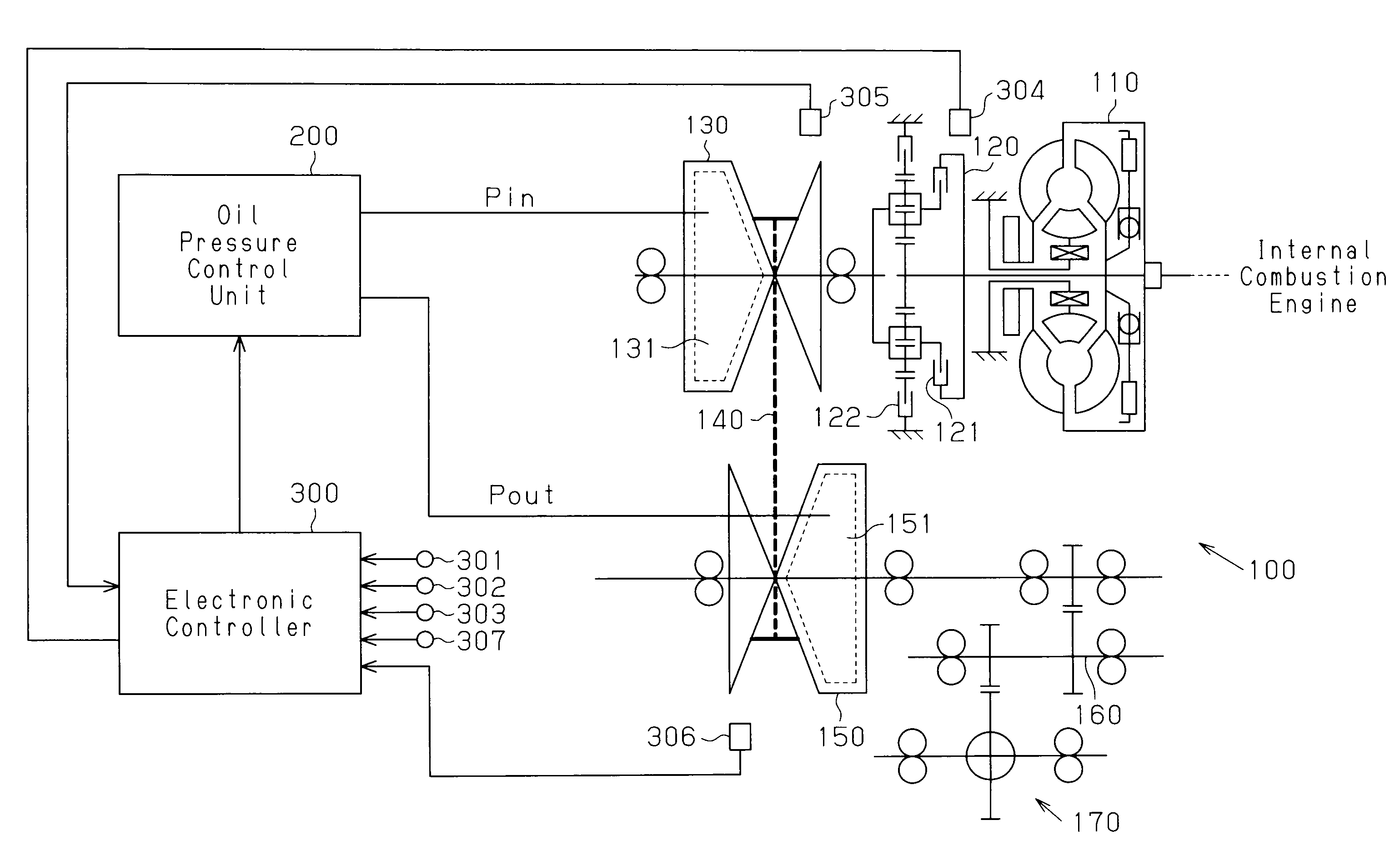
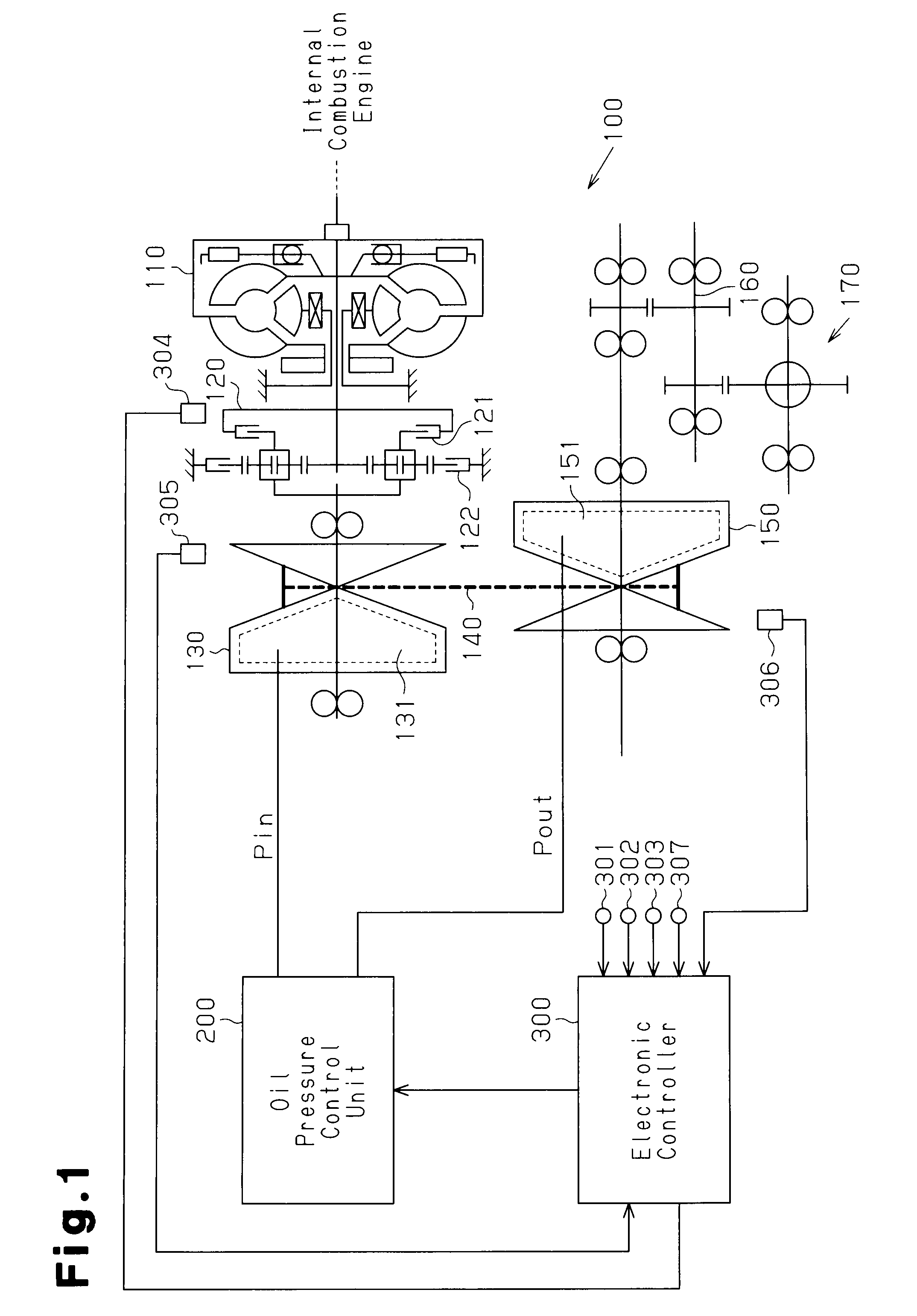
[0019]A vehicle continuously variable transmission according the present invention and embodied in an electronic controller that centrally controls a vehicle will now be described with reference to FIGS. 1 to 5.
[0020]FIG. 1 is a schematic diagram showing the structure of a continuously variable transmission 100 of the present embodiment and the relation between the continuously variable transmission 100 and an electronic controller 300, which controls the continuously variable transmission 100. As shown in FIG. 1, the continuously variable transmission 100 of the present embodiment includes a torque converter 110 with an output shaft connected to an input shaft of an forward-reverse switching mechanism 120.
[0021]The forward-reverse switching mechanism 120, which is a double pinion type planetary gearing mechanism, includes a forward clutch 121 and a reverse brake 122. When the forward clutch 121 is in an engaged state and the reverse brake 122 is in a disengaged state, the drive for...
PUM
 Abstract
Description
Claims
Application Information