Mechanically opening emergency parachute

a parachute and mechanical technology, applied in the field of parachutes, can solve the problems of increasing drag, slowing down the object, and not retaining the pilot chute after deploymen

Inactive Publication Date: 2011-09-15
SUH BONG H
View PDF17 Cites 17 Cited by
  • Summary
  • Abstract
  • Description
  • Claims
  • Application Information

AI Technical Summary

Problems solved by technology

As the thin material inflates it increases drag and in turn slowing down the object it is carrying.
Reserves, on the other hand, do not retain their pilot chutes after deployment.
This is known as a free-bag configuration, and the components are often lost during a reserve deployment.
Occasionally, a pilot chute does not generate enough force either to pull the pin or to extract the bag.
Causes may be that the pilot chute is caught in the turbulent wake of the jumper (the “burble”), the closing loop holding the pin is too tight, or the pilot chute is generating insufficient force.
This effect is known as “pilot chute hesitation,” and, if it does not clear, it can lead to a total malfunction, requiring reserve deployment.
If a parachute is not packed properly it can result in death because the main parachute might fail to deploy correctly or fully.
Most injuries and fatalities in sport skydiving occur under a fully functional main parachute because the skydiver made an error in judgment while flying the canopy, resulting in high-speed impact with the ground, impact with a hazard on the ground that might otherwise have been avoided, or collision with another skydiver under canopy.
Such malfunctions (and other accidents) are likely to occur when a parachute is deployed at too low an altitude, thus not allowing the parachute time to properly open and not providing sufficient drag to slow the user during the fall.
Conventional parachutes cannot be used in emergency situations, such as when a user must evacuate an office building, because of this limitation.
Even with the improvements of parachute 10 over conventional parachutes or umbrellas, parachute 10 may not provide transport and deployment in a manner that is efficient and quick enough to deal with a particular emergency situation.

Method used


Image

  • Mechanically opening emergency parachute
  • Mechanically opening emergency parachute
  • Mechanically opening emergency parachute

Examples


Embodiment Construction

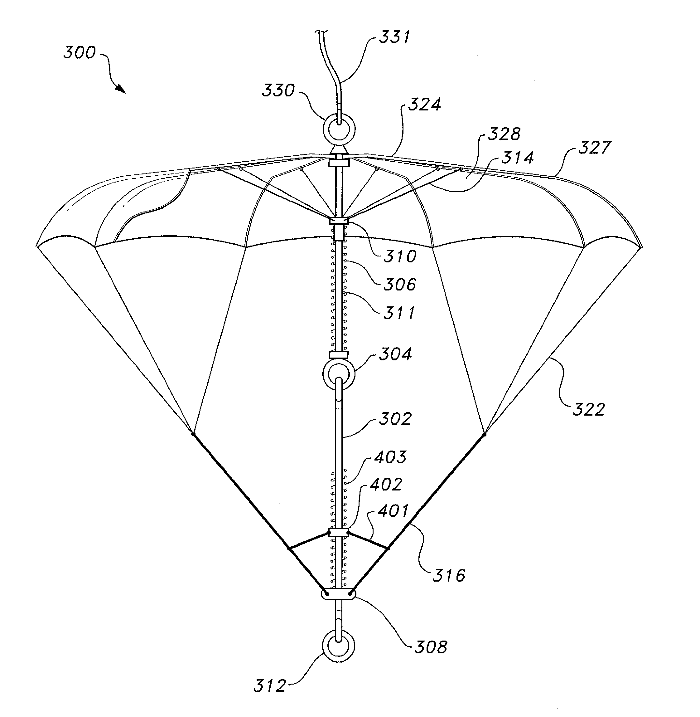
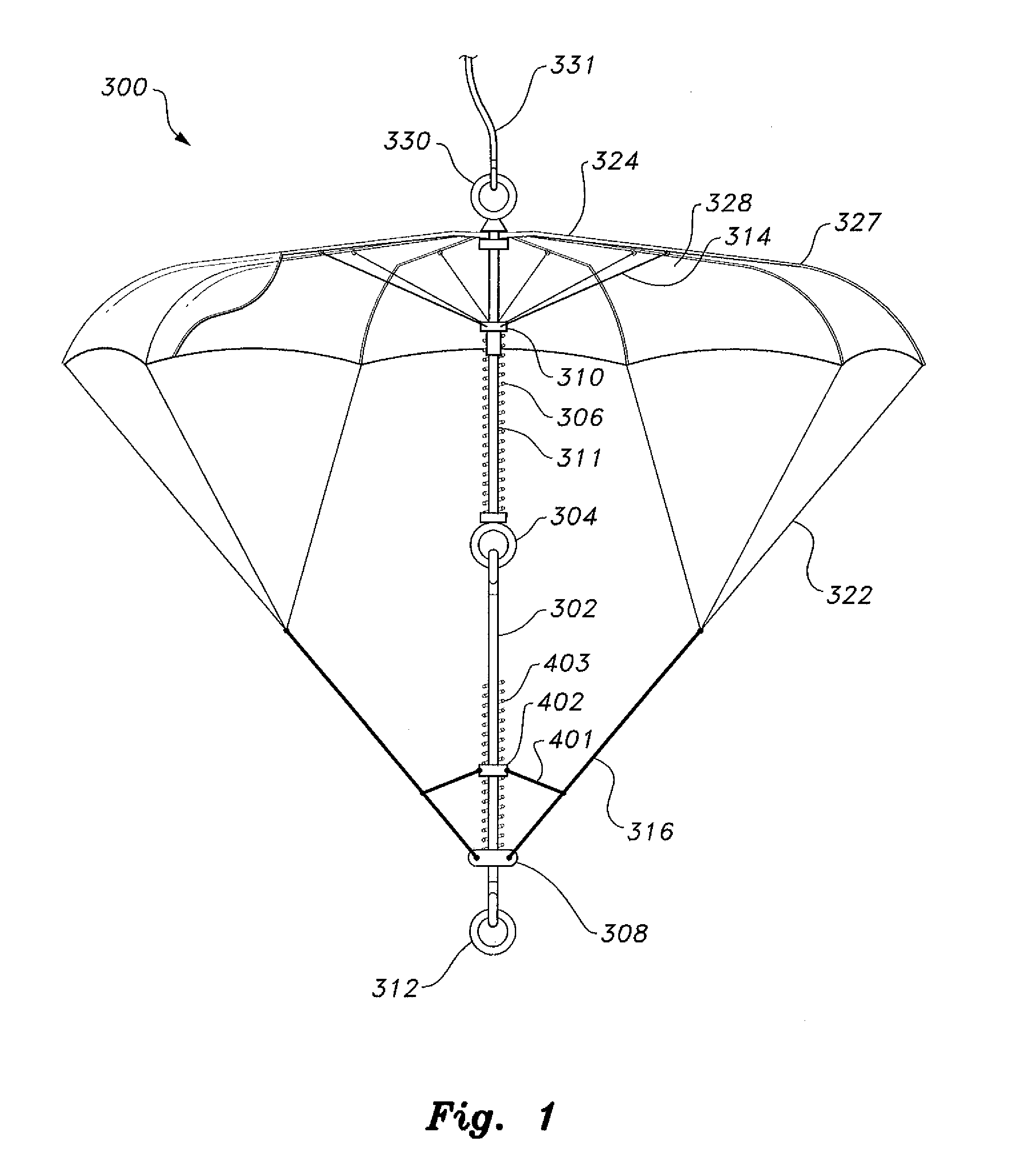
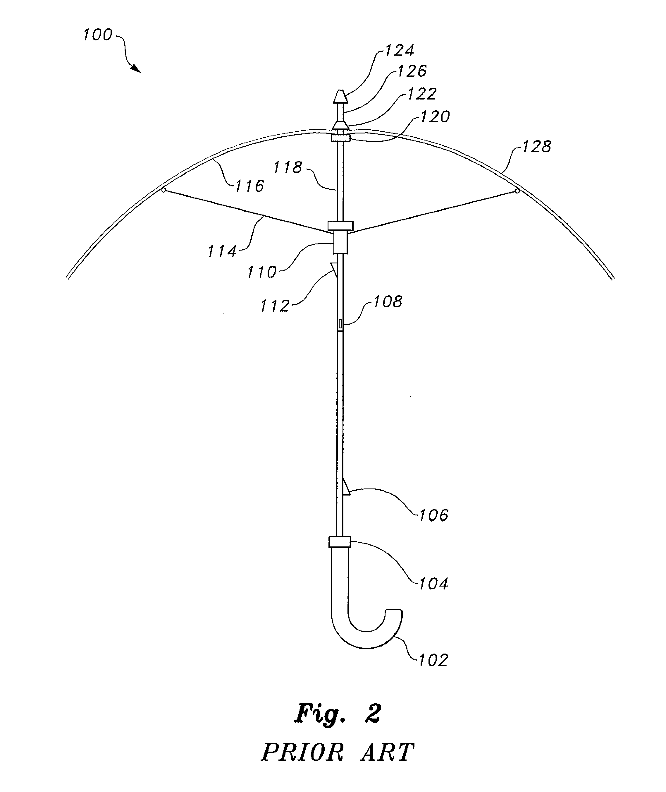
The mechanically opening emergency parachute 300, shown in FIGS. 1 and 8, is similar to the prior art mechanically opening parachute 10 of FIG. 7, however telescopic tube 18 is replaced by a tube 311, having opposed upper and lower ends, with a suspension cord 302 being tied or otherwise secured to lower end 304 thereof. It should be understood that suspension cord 302 may, alternatively, be removed. However, in the preferred embodiment, suspension cord 302 is secured to lower end 304. A ring or other mount 312 is provided on the lower end of the suspension cord 302, as shown, allowing for attachment of a harness, such as harness 12 of FIG. 7. The upper end 330 of tube 311 has a similar mount formed thereon, allowing for a cord or line 331 to be secured thereto. The cord or line 331 attached to upper end 330 may be fixed, at its other end, to the lower mount 312 of a second parachute 300, thus allowing multiple users to escape from an emergency situation together (as shown in FIG. 9...


PUM


Abstract

The mechanically opening emergency parachute is a parachute that may be opened quickly at low altitudes, such as during an emergency exit from an office building. The parachute includes a tube having opposed upper and lower ends, with an upper end of a suspension cord being secured to the lower end thereof. An upper annular runner is resiliently mounted on the tube. First ends of a plurality of ribs are pivotally attached to the upper end of the tube. An upper stretcher is mounted on the upper annular runner and includes a plurality of supports, with each support extending therefrom to one of the ribs. A lower stretcher is secured to the lower end of the suspension cord and includes a plurality of risers radially extending therefrom. A canopy is secured to the ribs, and a plurality of suspension lines extend between the risers and the canopy.

Description

BACKGROUND OF THE INVENTION1. Field of the InventionThe present invention relates to parachutes, and particularly to a mechanically opening emergency parachute that may be used quickly in emergency situations.2. Description of the Related ArtA parachute is a device used to slow the motion of an object through an atmosphere by creating drag. A parachute is made from thin, lightweight fabric, support tapes and suspension lines. The lines are usually gathered through cloth loops or metal connector links at the ends of several strong straps called risers. The risers in turn are attached to the harness containing the load. As the thin material inflates it increases drag and in turn slowing down the object it is carrying. The parachute successfully slows down the object enough so that it does not break on impact with the ground.Reserve parachutes usually have a ripcord deployment system, but most modern main parachutes used by sports parachutists use a form of hand-deployed pilot chute. A...

Claims


Application Information

Patent Timeline
Patent Type & Authority Applications(United States)
IPC IPC(8): B64D17/02B64D17/24B64D17/40B64D17/30
CPCB64D17/70A62B1/02
Inventor SUH, BONG H.
Owner SUH BONG H
Why Eureka
Try Eureka